Pioneer SA-5300 restoration: Part I. Dissasemble and Cleaning.
By isendev.
Posted on 2017/01/24 22:53.
Tagged as: audio, diy, vintage, pioneer.
This is one of my latest projects and my first approach to vintage audio equipment restoration. I recently got my hands on this beautiful 70's amplifier: a Pioneer SA-5300. This little japanese machine was made around 1975 and is capable of output 10 watts per channel (8 Ohms), with a frequency response of 20Hz to 30kHz and a total harmonic distortion of 0.08%. Apparently the amplifier is in good condition, and it will not take much work to make it shiny and working.
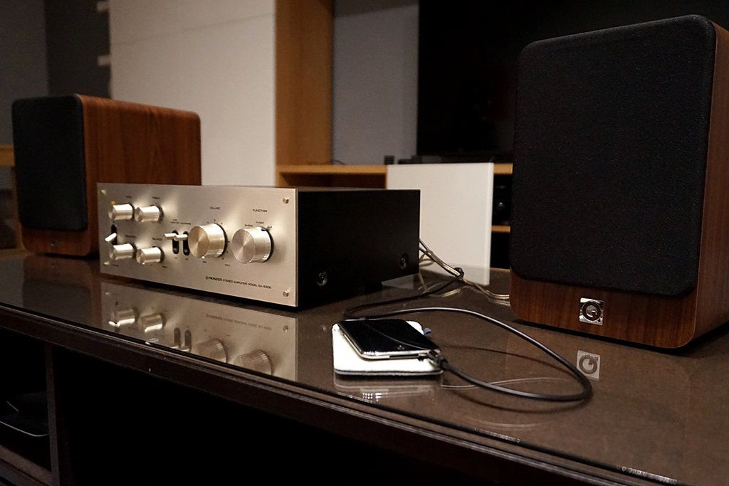
Once at home, I was able to test the amplifier paired with my trusty Q-Acoustics 2020i speakers. First impression was very positive. Nice sound, warm and detailed. Really impressive for a Pioneer "entry level" model. Beats hands down the stereo capabilities of my mid-range 2014 Yamaha home cinema receiver. The power bulb is blown and seems to have some minor problems on left channel when using the volume knob (nothing a good contact cleaner can not solve). Apart from those little problems, I have not found anything really important.
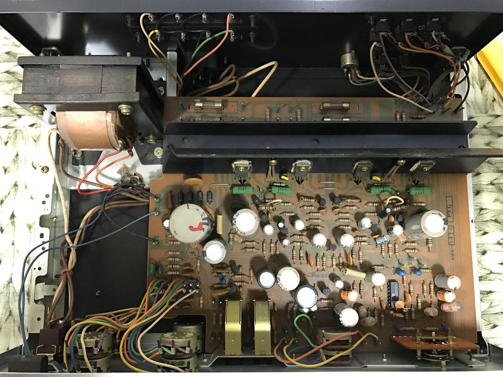
The image above shows the simplicity of the amplifier's internal layout: an AC transformer, front panel basic controls (switches and potentiometers), three input/output panels on the back and all these elements connected to only one board. This PCB shows the same level of simplicity as the rest of the unit, with evenly distributed components and thick tracks. Great for beginners who want to start learning how to restore vintage electronic equipment.
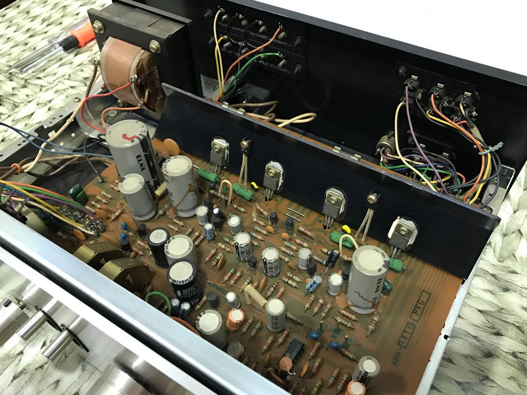
A first pass of compressed air removes all dust accumulated over the years, but in order to clean the all the grim properly (using water and soap), some components must be disconnected from the chassis. For example, to remove the back panel, some cables must be dettached from its connectors and resoldered on reassemble.
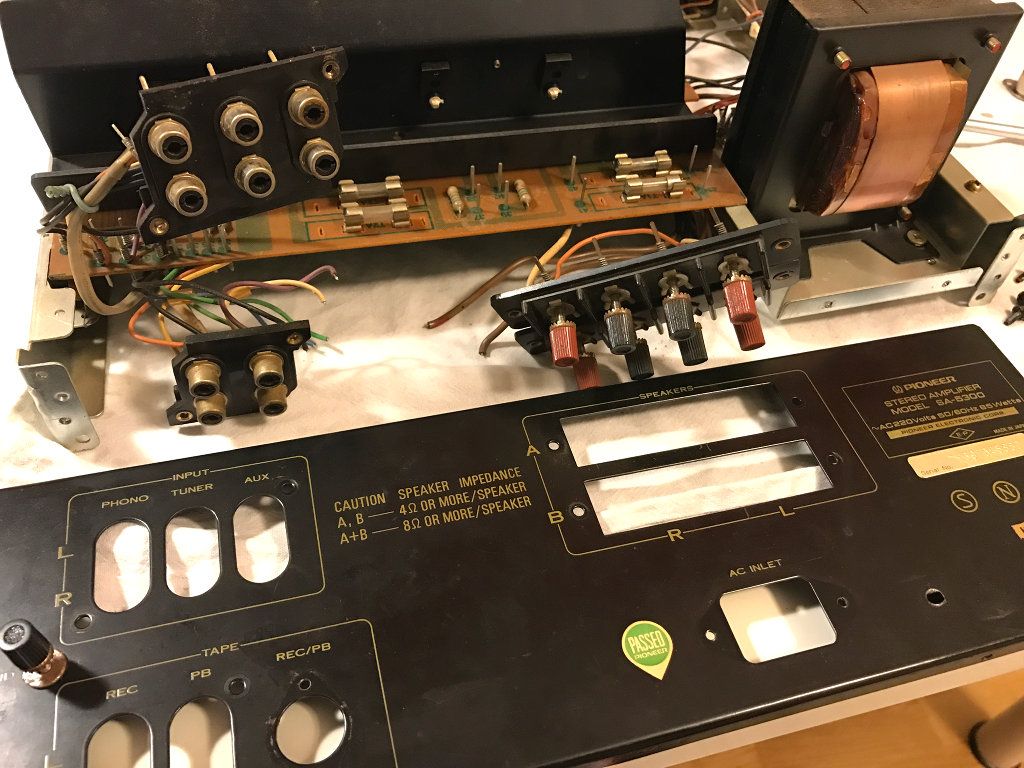
To replace the aged thermal grease on the transistors, the aluminium heatsink must be detached from the PCB. Special care must be taken when separating the transistors from the aluminum surface and when cleaning the traces of thermal grease: it's very easy to damage transistor's legs.
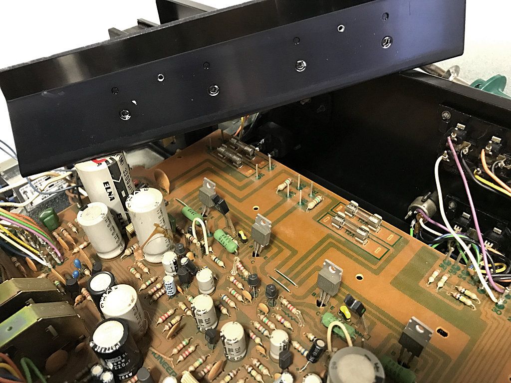
Once aged compound has been removed from heatsink and transistors, it's time to reassemble using brand new mica insulating washers and fresh thermal grease. The detailed cleaning of the rest of the components is done using soft brushes and PCB cleaner.
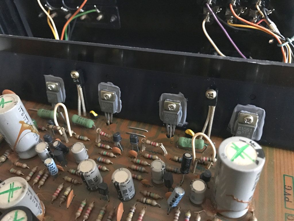
After cleaning is completed, the next step will be to replace all electrolytic capacitors. Why? Capacitors are the most failure-prone components in old electronic equipment, and is a common practice to replace all of a set's electrolytic capacitors to restore the original performance. In the next blog entry I will explain how I have done this recapping task.