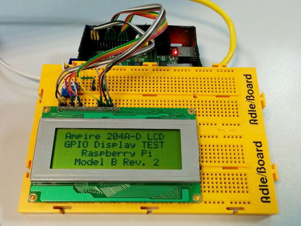
Raspberry Pi + LCD + Python
By isendev.
Posted on 2013/12/30 23:18.
Tagged as: hardware, programming, diy, python.

Looking through component boxes in my storage room, I found an Ampire 20x4 LCD (without backlight) that I had bought for an old MP3 Player project. My first thought was to throw the part to the junk box, but it was a shame without giving it any use.
The display uses a compatible Hitachi HD44780 LCD controller capable to address the alphanumeric matrix. It has a simple interface that can be connected to a general purpose microcontroller (or microprocessor). The physical connection is made through a standard 16 contact interface, with pins on 2.54mm. centers.
So, what about connecting the display to the Raspberry Pi and show something on it? Seems not a bad idea to start, and there´s a lot information about this subject on the net.
Following the directions and schematics published by Matt Hawkins on his site Raspberry Pi Spy, it's pretty straightforward to connect the LCD to the Raspberry Pi (in 4 bit mode) with the help of some wiring cable, a breadboard and a variable resistor. The connection uses 6 GPIO pins for communication purposes and 2 GPIO pins more for power.
Once connected, it´s only necessary to execute some lines of Python code to show a "Hello" message. The code uses the Raspberry Pi´s GPIO Library (RPi.GPIO) to make the access to GPIO pins pretty straightforward. RPi.GPIO is installed by default in the standard Debian Linux distribution.
#!/usr/bin/python
# 20x4 LCD Test Script for Raspberry Pi.
# Original code by: Matt Hawkins
# Site: http://www.raspberrypi-spy.co.uk
# Modified by: Antonio Perdices
# Site: https://www.isendev.com
# 30/12/2013

# LCD Wiring.
# 1 : GND                    - TO GROUND
# 2 : 5V                     - TO +5V
# 3 : Contrast (0-5V)        - TO 10K POT OUTPUT
# 4 : RS (Register Select)
# 5 : R/W (Read Write)       - TO GROUND
# 6 : Enable or Strobe
# 7 : Data Bit 0             - NOT USED
# 8 : Data Bit 1             - NOT USED
# 9 : Data Bit 2             - NOT USED
# 10: Data Bit 3             - NOT USED
# 11: Data Bit 4
# 12: Data Bit 5
# 13: Data Bit 6
# 14: Data Bit 7
# 15: Backlight 5V           - NOT USED
# 16: Backlight GND          - NOT USED

# Imports.
import RPi.GPIO as GPIO
import time

# GPIO to LCD Mapping.
# Using Broadcom GPIO numbers
LCD_RS = 7
LCD_E  = 8
LCD_D4 = 25
LCD_D5 = 24
LCD_D6 = 23
LCD_D7 = 18

# Constants.

# Max chars per line.
LCD_WIDTH = 20

# LCD Byte Mode. 'Character' or 'Command'.
LCD_CHR = True
LCD_CMD = False

# 1st Line LCD RAM address.
LCD_LINE_1 = 0x80
# 2nd Line LCD RAM address.
LCD_LINE_2 = 0xC0
# 3rd Line LCD RAM address.
LCD_LINE_3 = 0x94
 # 4th Line LCD RAM address.
LCD_LINE_4 = 0xD4

# Timing constants.
E_PULSE = 0.00005
E_DELAY = 0.00005

# Main program.
def main():

    # Disable warnings.
    GPIO.setwarnings(False)

    # Use Broadcom GPIO numbers.
    GPIO.setmode(GPIO.BCM)

    # Enable GPIO outputs.
    GPIO.setup(LCD_E, GPIO.OUT)  # E
    GPIO.setup(LCD_RS, GPIO.OUT) # RS
    GPIO.setup(LCD_D4, GPIO.OUT) # DB4
    GPIO.setup(LCD_D5, GPIO.OUT) # DB5
    GPIO.setup(LCD_D6, GPIO.OUT) # DB6
    GPIO.setup(LCD_D7, GPIO.OUT) # DB7

    # Init display.
    lcd_init()

    # TEST. Write some lines.
    lcd_byte(LCD_LINE_1, LCD_CMD)
    lcd_string("Ampire 204A-D LCD",2)
    lcd_byte(LCD_LINE_2, LCD_CMD)
    lcd_string("GPIO Display TEST",2)
    lcd_byte(LCD_LINE_3, LCD_CMD)
    lcd_string("Raspberry Pi",2)
    lcd_byte(LCD_LINE_4, LCD_CMD)
    lcd_string("Model B Rev. 2",2)

    # Cleaning Up.
    # GPIO.cleanup()

# Init display function.
def lcd_init():

    # Init commands.
    lcd_byte(0x33,LCD_CMD)
    lcd_byte(0x32,LCD_CMD)
    lcd_byte(0x28,LCD_CMD)
    lcd_byte(0x0C,LCD_CMD)
    lcd_byte(0x06,LCD_CMD)
    lcd_byte(0x01,LCD_CMD)

# Send byte data to display.
# bits = data.
# mode = 'True' for character or 'False' for command.
def lcd_byte(bits, mode):

    # Register Select.
    GPIO.output(LCD_RS, mode)

    # Send High bits.
    GPIO.output(LCD_D4, False)
    GPIO.output(LCD_D5, False)
    GPIO.output(LCD_D6, False)
    GPIO.output(LCD_D7, False)
    if bits&0x10==0x10:
        GPIO.output(LCD_D4, True)
    if bits&0x20==0x20:
        GPIO.output(LCD_D5, True)
    if bits&0x40==0x40:
        GPIO.output(LCD_D6, True)
    if bits&0x80==0x80:
        GPIO.output(LCD_D7, True)

    # Toggle 'Enable' pin.
    time.sleep(E_DELAY)
    GPIO.output(LCD_E, True)
    time.sleep(E_PULSE)
    GPIO.output(LCD_E, False)
    time.sleep(E_DELAY)

    # Low bits.
    GPIO.output(LCD_D4, False)
    GPIO.output(LCD_D5, False)
    GPIO.output(LCD_D6, False)
    GPIO.output(LCD_D7, False)
    if bits&0x01==0x01:
        GPIO.output(LCD_D4, True)
    if bits&0x02==0x02:
        GPIO.output(LCD_D5, True)
    if bits&0x04==0x04:
        GPIO.output(LCD_D6, True)
    if bits&0x08==0x08:
        GPIO.output(LCD_D7, True)

    # Toggle 'Enable' pin
    time.sleep(E_DELAY)
    GPIO.output(LCD_E, True)
    time.sleep(E_PULSE)
    GPIO.output(LCD_E, False)
    time.sleep(E_DELAY)

# Send string to display.
# Style parameter:
# 1 = Left justified.
# 2 = Centred.
# 3 = Right justified.
def lcd_string(message,style):

    if style==1:
        message = message.ljust(LCD_WIDTH," ")
    elif style==2:
        message = message.center(LCD_WIDTH," ")
    elif style==3:
        message = message.rjust(LCD_WIDTH," ")

    for i in range(LCD_WIDTH):
        lcd_byte(ord(message[i]),LCD_CHR)

# Execute main program.
if __name__ == '__main__':
    main()