Showing entries tagged as: audio
WIMA Capacitors cMoy build.
By isendev.
Posted on 2012/11/27 18:58.
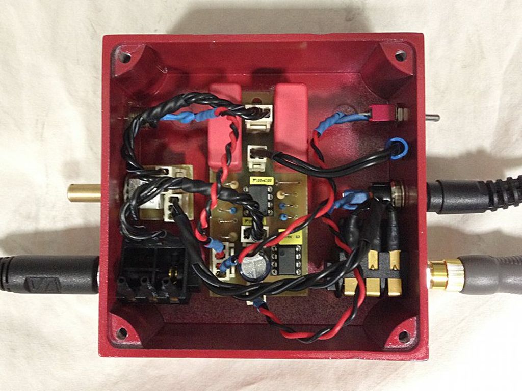
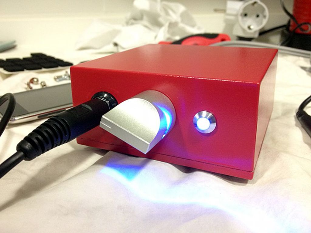
This is the completed build of my CMoy headphone amplifier. It uses a custom PCB layout designed around a pair of WIMA MKP 10 input capacitors. Board and associated accessories (volume pot, stereo jacks, LED holder, power switch, etc.) have been installed inside a Hammond 70009 enclosure.
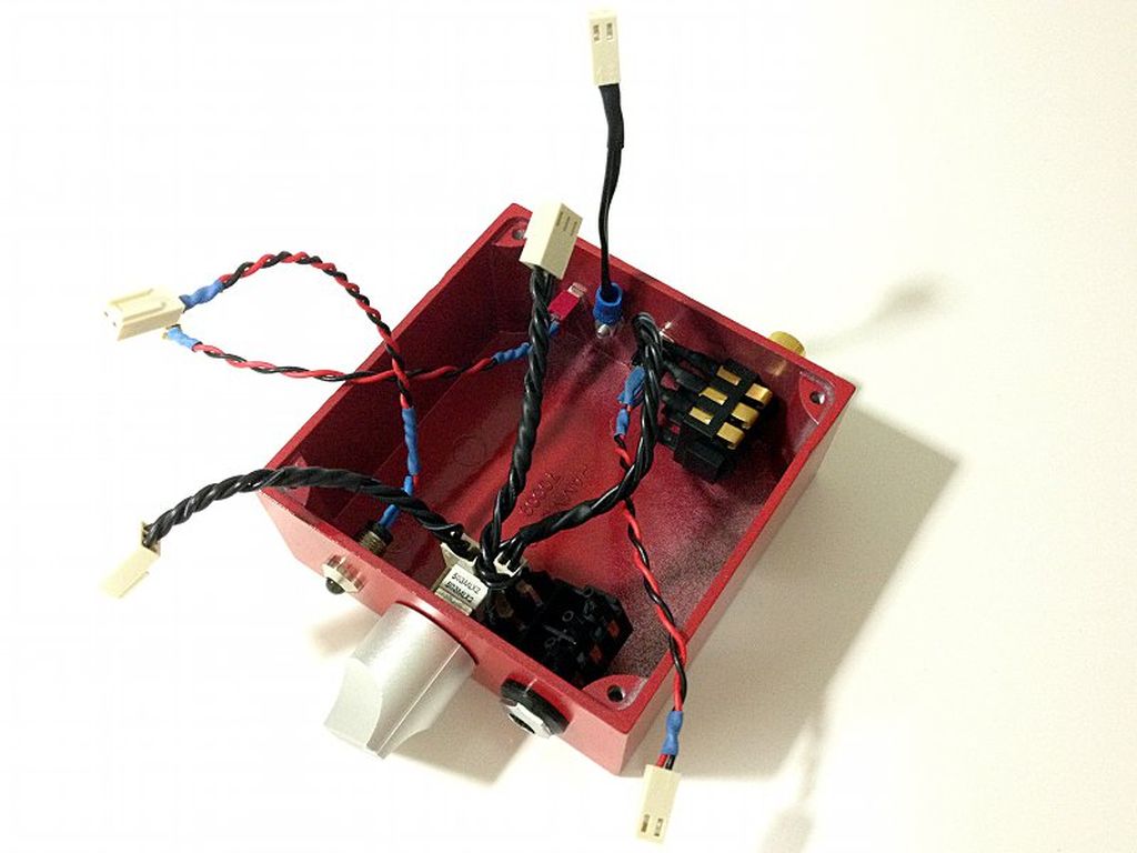
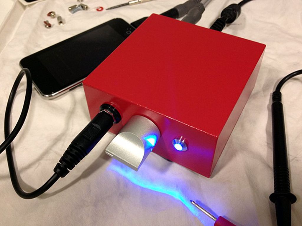
More photos of the final result:
My new cMoy PCB.
By isendev.
Posted on 2012/09/20 18:05.
This is the PCB for my second custom CMoy build. It uses a pair of WIMA MKP 10 as input capacitors and is ready to be installed on my recently finished Hammond 70009 enclosure.
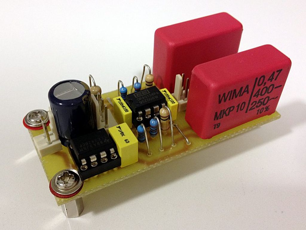
This is the part list used in this build:
- Power section:
- 1 x Panasonic FC 470uF. 25V. electrolythic capacitor.
- 1 x Texas Instruments TLE2426CP rail splitter.
- 1 x DIP8 socket.
- 1 x Generic 1uF. 63V. polyester capacitor (TLE noise reduction).
- 3 x Molex KK 2 pin vertical male connectors (power input connector, power switch connector and LED connector).
- 2 x WIMA MKP 10 - 0.47uF. 400V. - Polypropylene (PP) film dielectric (input capacitors).
- 1 x Texas Instruments / Burr-Brown OPA2134PA Op-Amp.
- 2 x Generic 0.1uF. 100V. polyester capacitor (Op-Amp decoupling capacitors).
- 1 x DIP8 socket.
- 2 x Molex KK 3 pin vertical male connectors (audio input / output connectors).
- 1 x Molex KK 2 pin vertical male connectors (ground connector).
- 2 x Generic 100K. 1/4W. resistor.
- 2 x Generic 10K. 1/4W. resistor.
- 2 x Generic 2.2K. 1/4W. resistor.
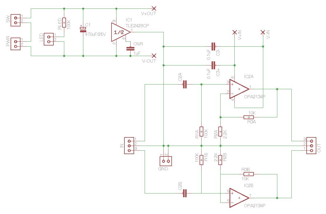
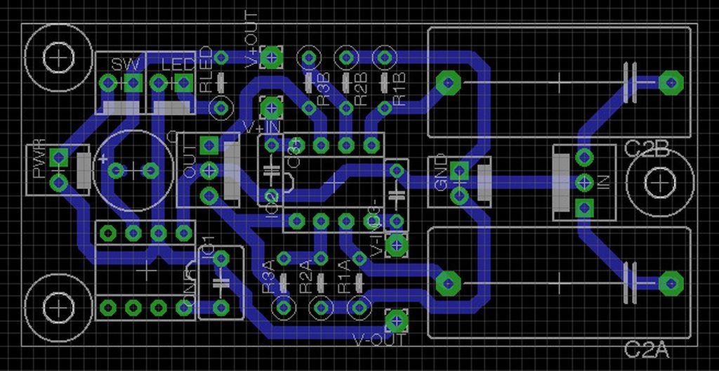
My new cMoy case.
By isendev.
Posted on 2012/07/26 18:10.
I've been working in a case for my new cMoy build using a Hammond 70009 diecast aluminum enclosure. This is an IP54 compliant box with dimensions of 92 x 92 x 38 millimeters. To install all the in/out connectors, holes were drilled around the case using a drill press.
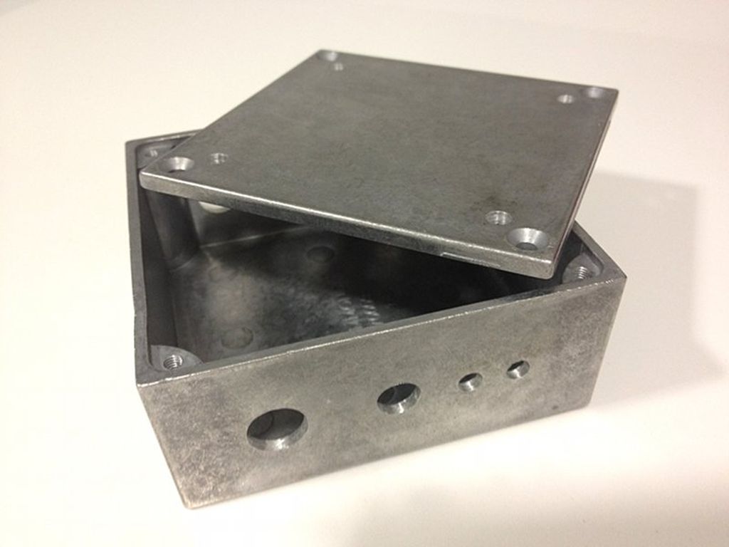
After that, the paint process started: Two acid primer coats and 600 grit wet sanding were required to prepare the surface.
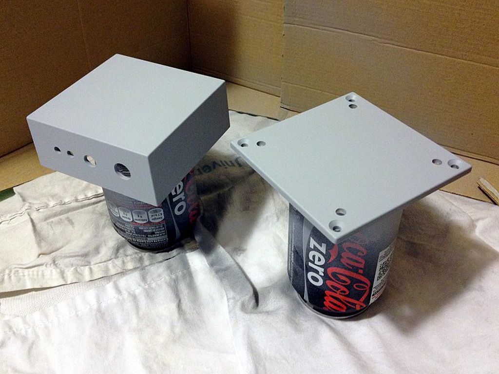
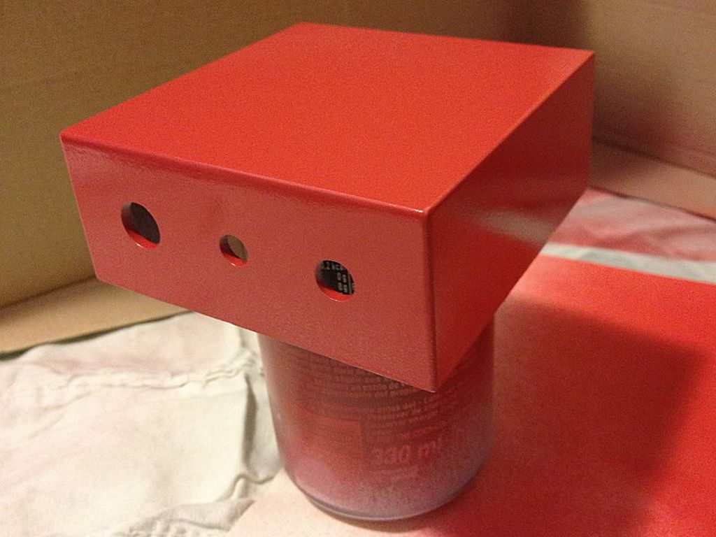
After deeply cleaning the parts to remove all the sanding dust, acrylic paint and clear coats were applied to obtain a sleek glossy finish.
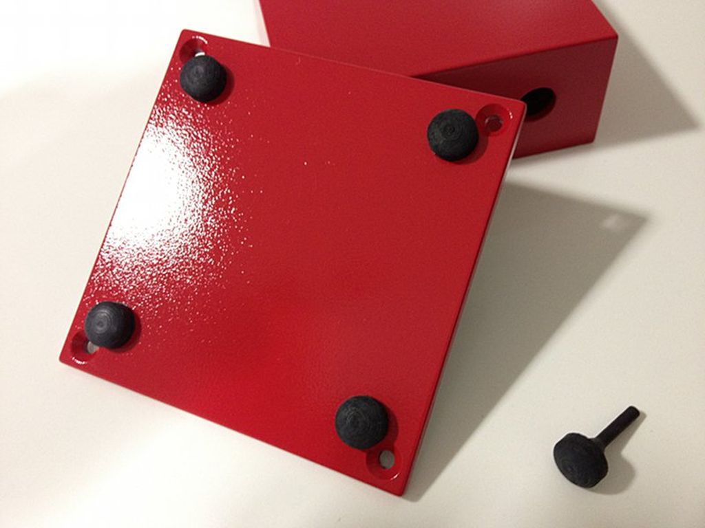
Finally, I installed four through-hole rubber pads on the bottom cover to prevent the enclosure from sliding off the table. Now, It's ready to house the cMoy PCB and its stuff (cables, connectors and switches).
My first CMoy build.
By isendev.
Posted on 2012/03/27 01:52.
Now I'm working on a second revision of my custom CMoy build, but before posting more details about it, I want to recap some information of my original build from April 2010.
But first of all... What's a CMoy?
Taken from the Wikipedia:
A CMoy is a pocket headphone amplifier originally designed by Chu Moy on the headwize.com Headphone Resource Site and public discussion Forums. The headphone amplifier is designed around single or dual-channel op-amps such as Burr-Brown's OPA2134 or OPA2132PA, however, a wide variety of op-amps have been successfully implemented. The amplifier's design is quite simple. It consists of only a few components, can be assembled on a small section of protoboard, has a lower parts cost than other headphone amplifiers, and can run for many hours on a single 9 volt battery.I was searching for a simple electronic schematic to test the tone-transfer method for etching printed circuit boards at home, and this small headphone amplifier was a good point to start. I found tons of information about it at headwize.com and diyaudio.com community forums but, without a doubt, the best resource was Tangensoft's website. There you can find the most complete guide to design and build your own CMoy.
And here is my original Eagle PCB layout. It's easy to see the main modification done to the basic CMoy design: I used a rail splitter IC instead of a resistor bridge to obtain the required voltage levels for running the op-amp.
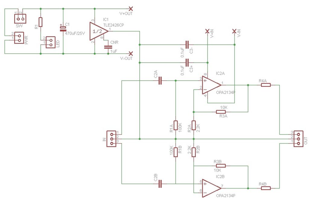
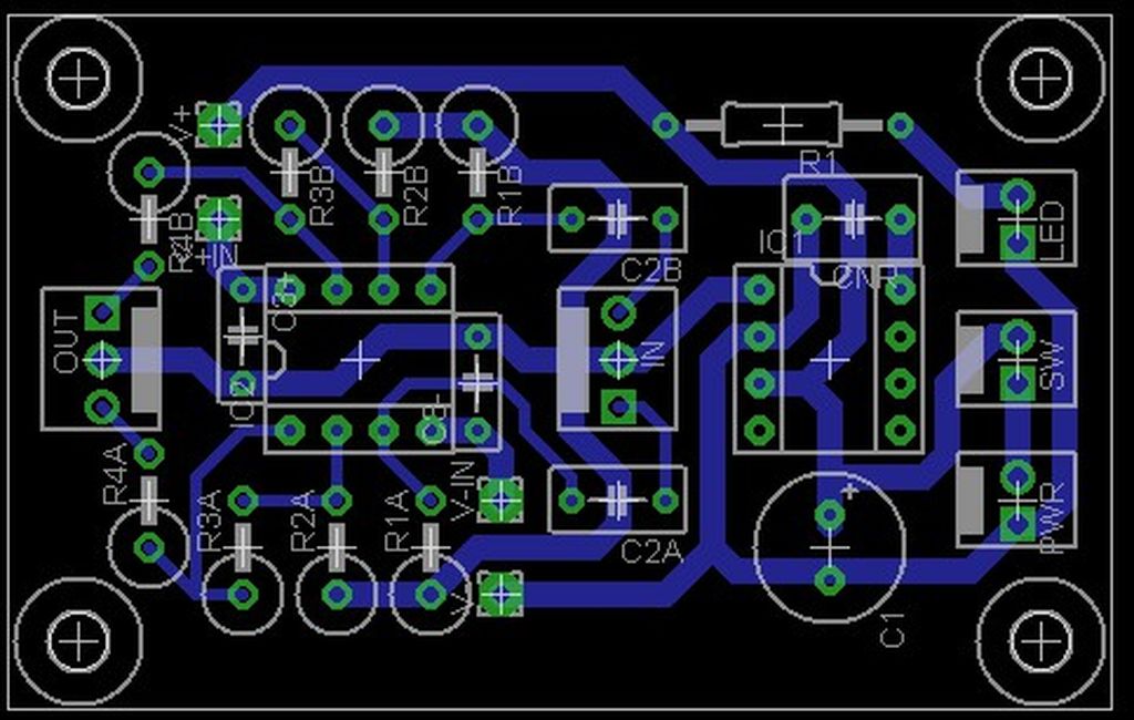
This is the full component list used in my build:
- Power section:
- 1 x Panasonic FC 470uF. 25V. electrolythic capacitor.
- 1 x Texas Instruments TLE2426CP rail splitter.
- 1 x DIP8 socket.
- 1 x Generic 1uF. 63V. polyester capacitor (TLE noise reduction).
- 3 x Molex KK 2 pin vertical male connectors (power input connector, power switch connector and LED connector).
- 2 x Matsushita/Panasonic metallized polyester film capacitor ECQE Series - 0.1uF./100V. - Mylar PET dielectric (input capacitors).
- 1 x Texas Instruments / Burr-Brown OPA2134PA Op-Amp.
- 2 x Generic 0.1uF. 100V. polyester capacitor (Op-Amp decoupling capacitors).
- 1 x DIP8 socket.
- 2 x Molex KK 3 pin vertical male connectors (audio input / output connectors).
- 2 x Generic 100K. 1/4W. resistor.
- 2 x Generic 10K. 1/4W. resistor.
- 2 x Generic 2.2K. 1/4W. resistor.
- 1 x M223-RS 6.5mm. female switched stereo connector - chassis mount (audio output jack).
- 1 x Generic 3.5mm. female stereo connector - chassis mount (audio input jack).
- 1 x Vishay P9A Series 100mW. 10K. logarithmic dual potentiometer - chassis mount (audio input attenuation).
- 1 x Generic 5mm. red LED.
- 1 x Generic 5mm. LED holder - chassis mount.
- 1 x Generic 100K. 1/4W. resistor (LED resistor).
- 1 x Generic switch - chassis mount.
- 1 x Generic power Socket - chassis mount.
- 3 x Molex KK 2 pin female connectors (power input jack, power switch and LED holder).
- 2 x Molex KK 3 pin female connectors (audio input / output jacks).
- 1 x Generic 12V. 1.25A. wall wart (power supply).
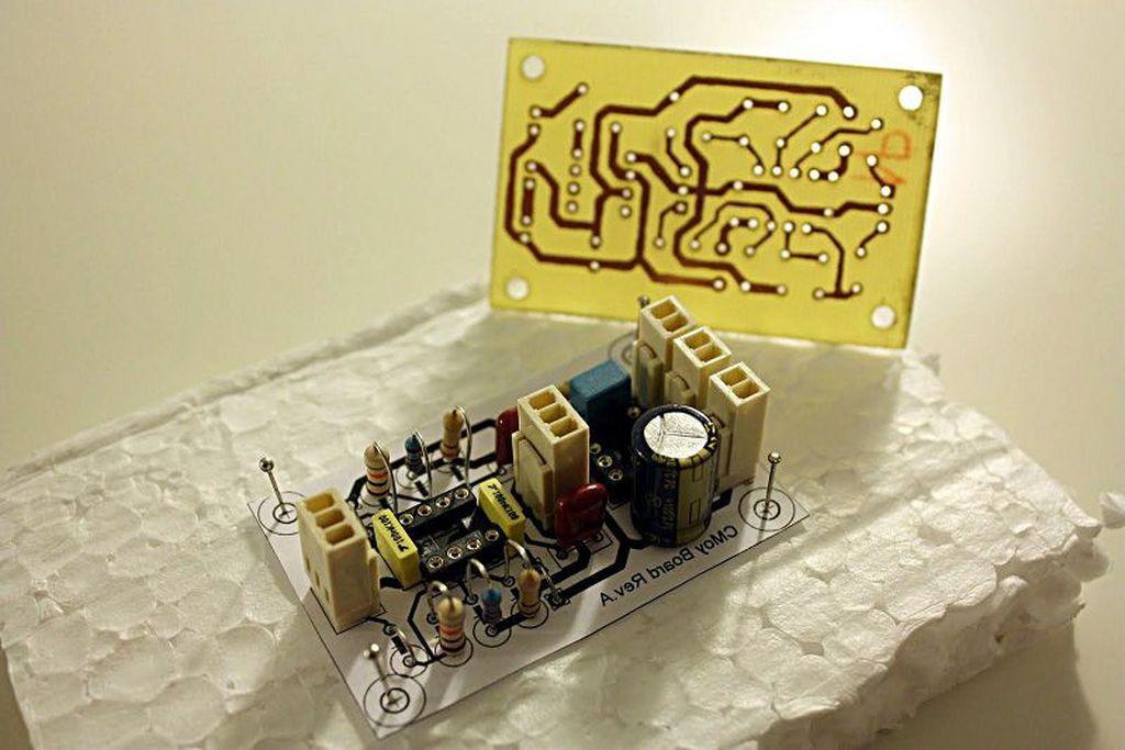
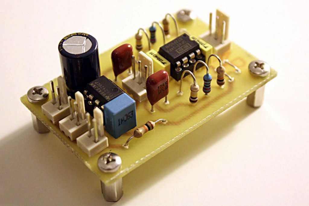
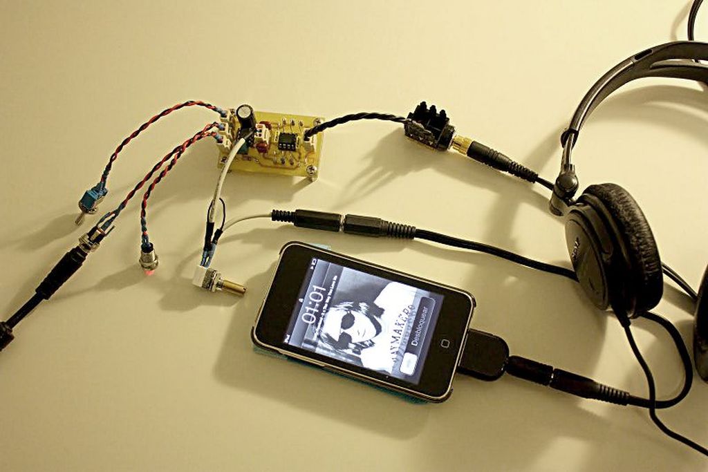
After some testing, a few changes were done to the board:
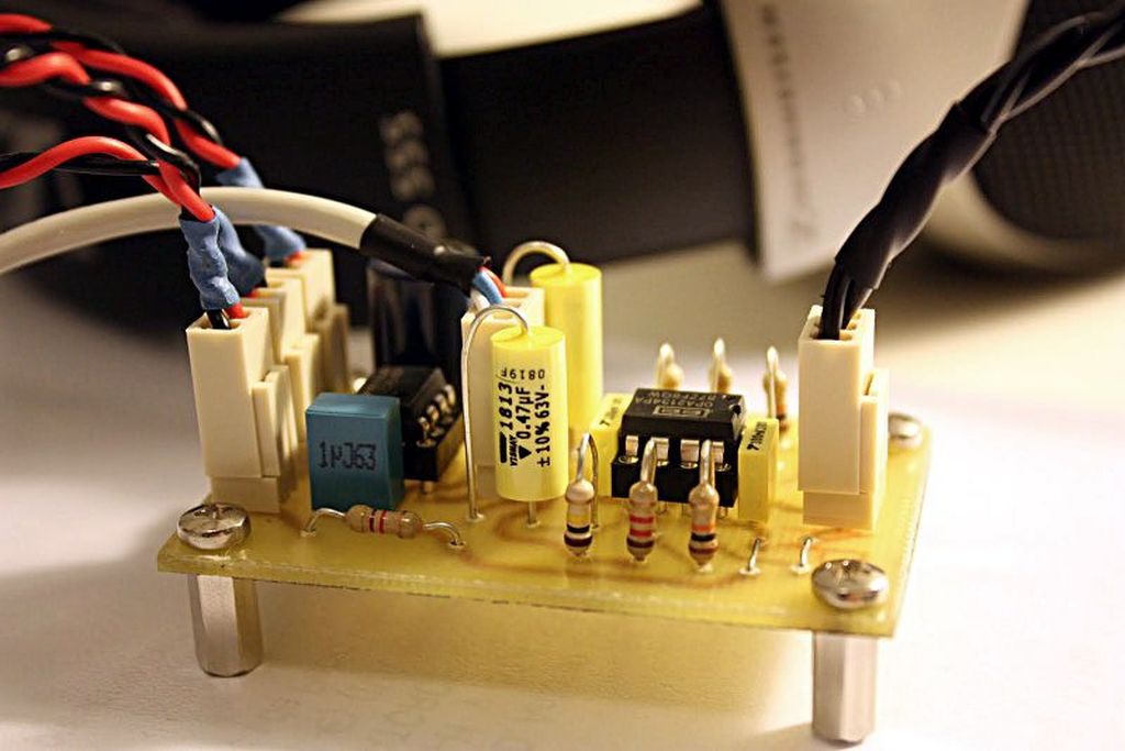
- 2.2K Resistors were replaced by 1.2K. resistors to modify CMoy´s gain ((10/1.2) + 1 = 9.3dB.) and improve the output volume using the iPod stereo jack.
- Panasonic ECQE 0.1uF./100V. input capacitors were replaced by Vishay MKT 0.47uF./63V. capacitors to improve bass handling.
- 10K. 1/4W. LED resistor was replaced by 4.7K. 1/4W. resistor to make the power LED brighter.
