Showing entries tagged as: vintage
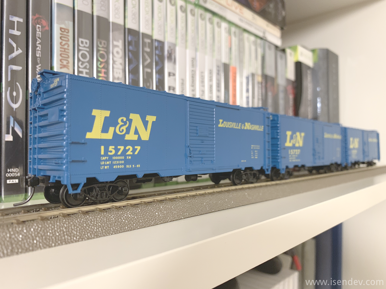
Building an Accurail kit: 40' L&N AAR Steel Box Car.
By isendev.
Posted on 2019/06/04 23:18.
Tagged as: vintage, railwaymodelling.
After a long time, I've returned back to my old hobby of railway modelling. When I was young, I spent countless hours playing with my dad's collection and now, in my forties, I would like to start my own collection with some american model trains.
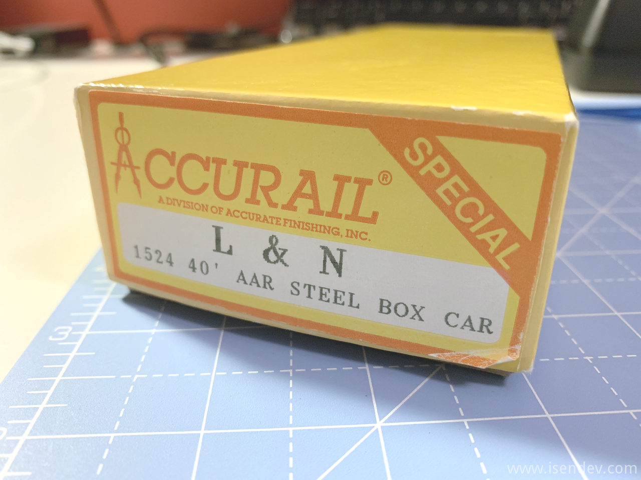
It is difficult to find such models for sale in Spain, but looking from time to time on auction sites, you sometimes get an offer that is worthwhile. Back in January, I found a set of 6 x 40' AAR (Association of American Railroads) standard box car kits. These kits were made in 1995 by Accurail (Ref. 1524) and decorated with the L&N (Louisville & Nashville Railroad) colors. They are easy to assemble and should not take more than half an hour to complete each of them.
Here are some photos and information about the building process of one of this Accurail box car kits. Note that wheelsets and couplers have been upgraded to Kadee parts.
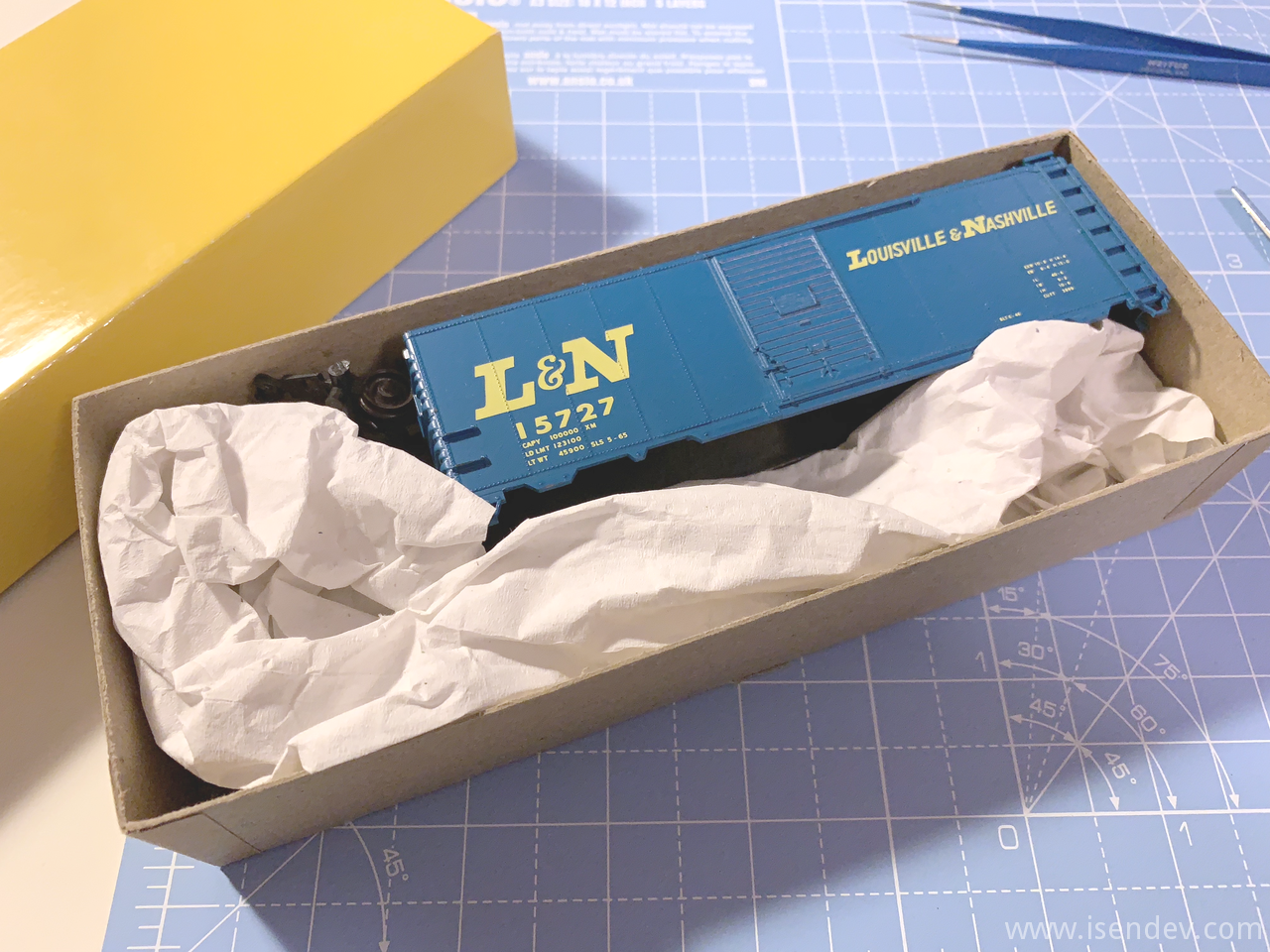
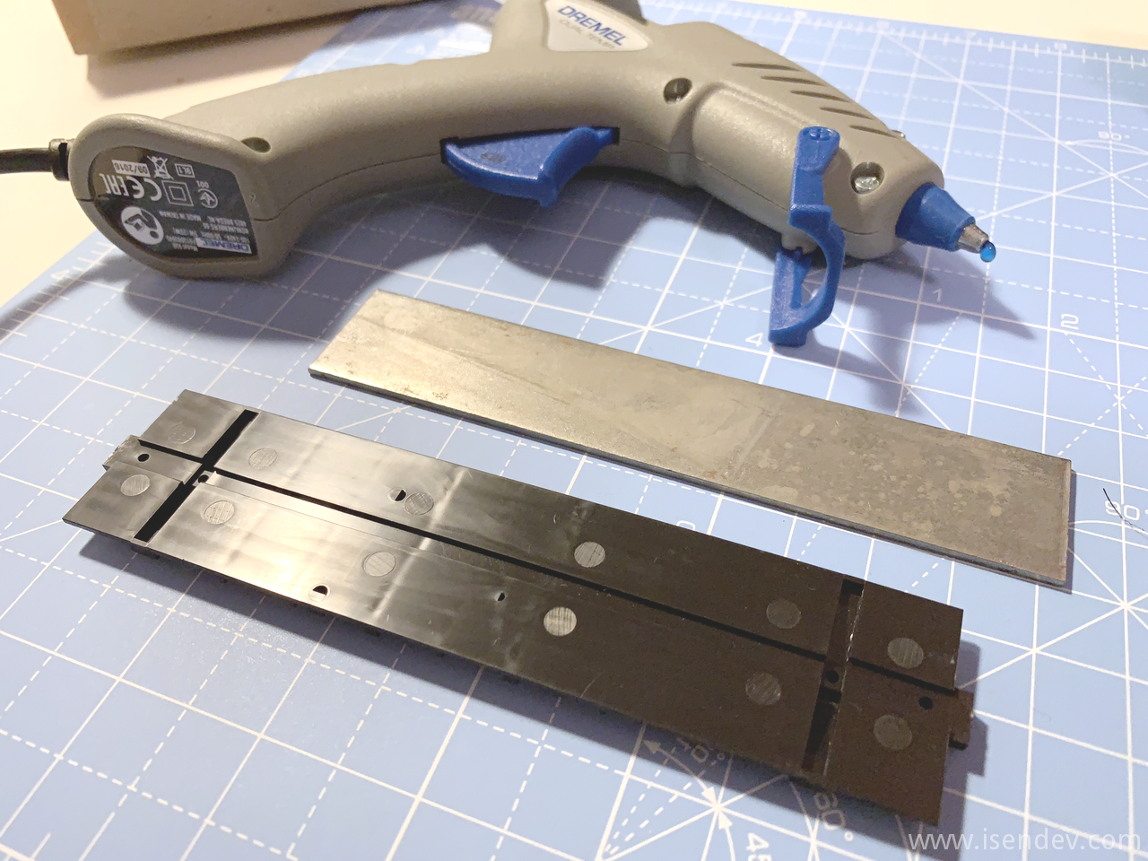
All kits came in its original box and with all its contents intact. Time to prepare glue and tooling for building one of them.
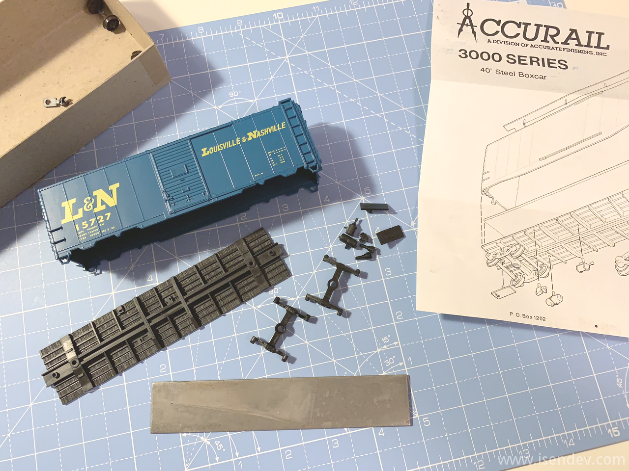
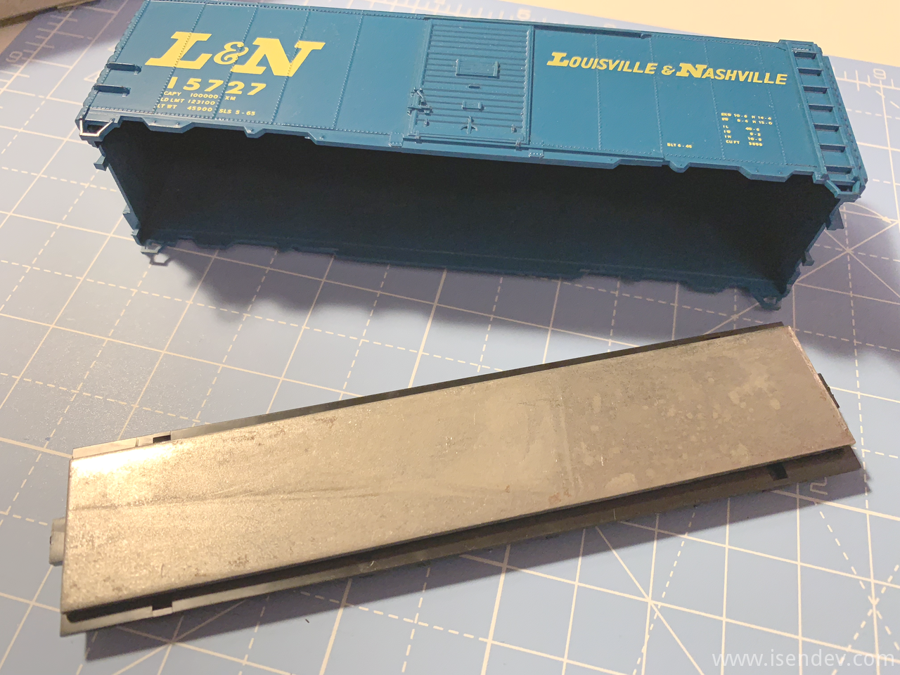
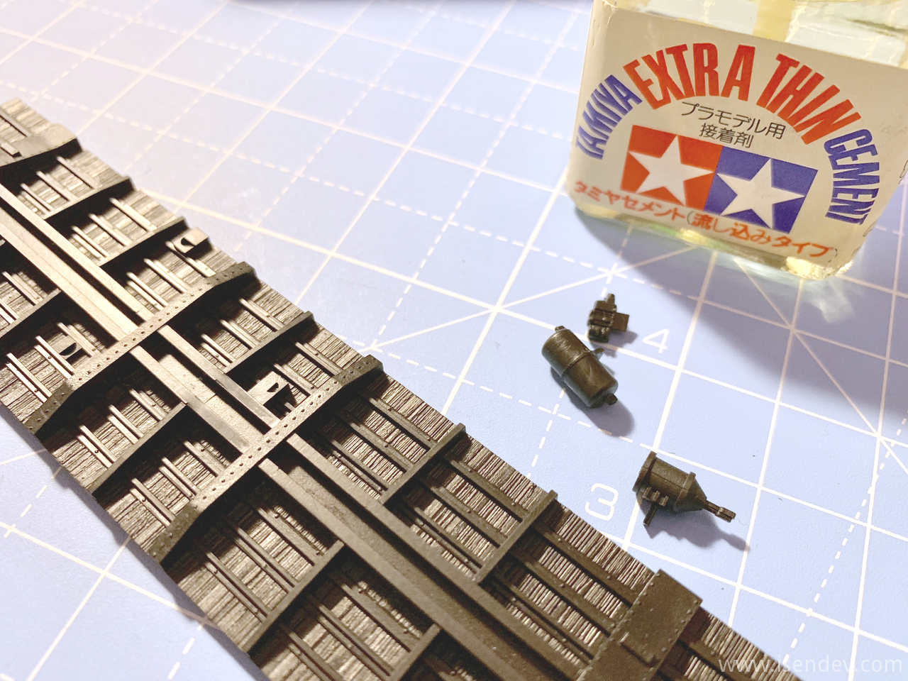
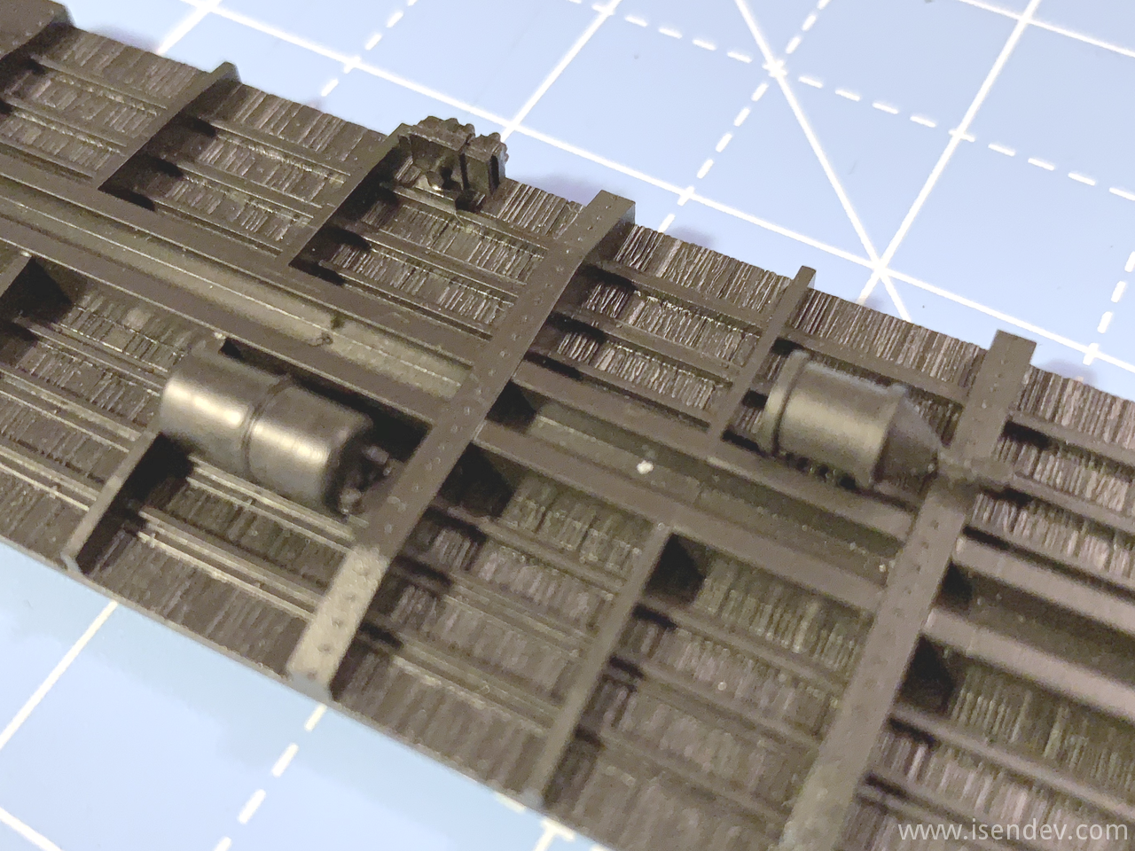
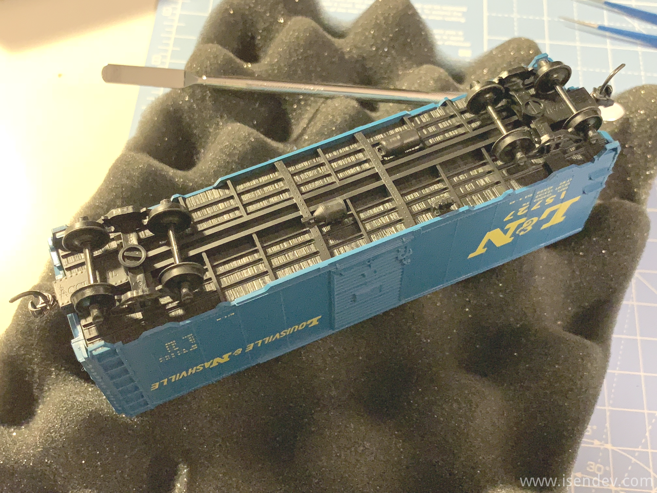
I've attached the weight to the car box chassis using hot glue and the additional under frame accesories using Tamiya extra thin cement.
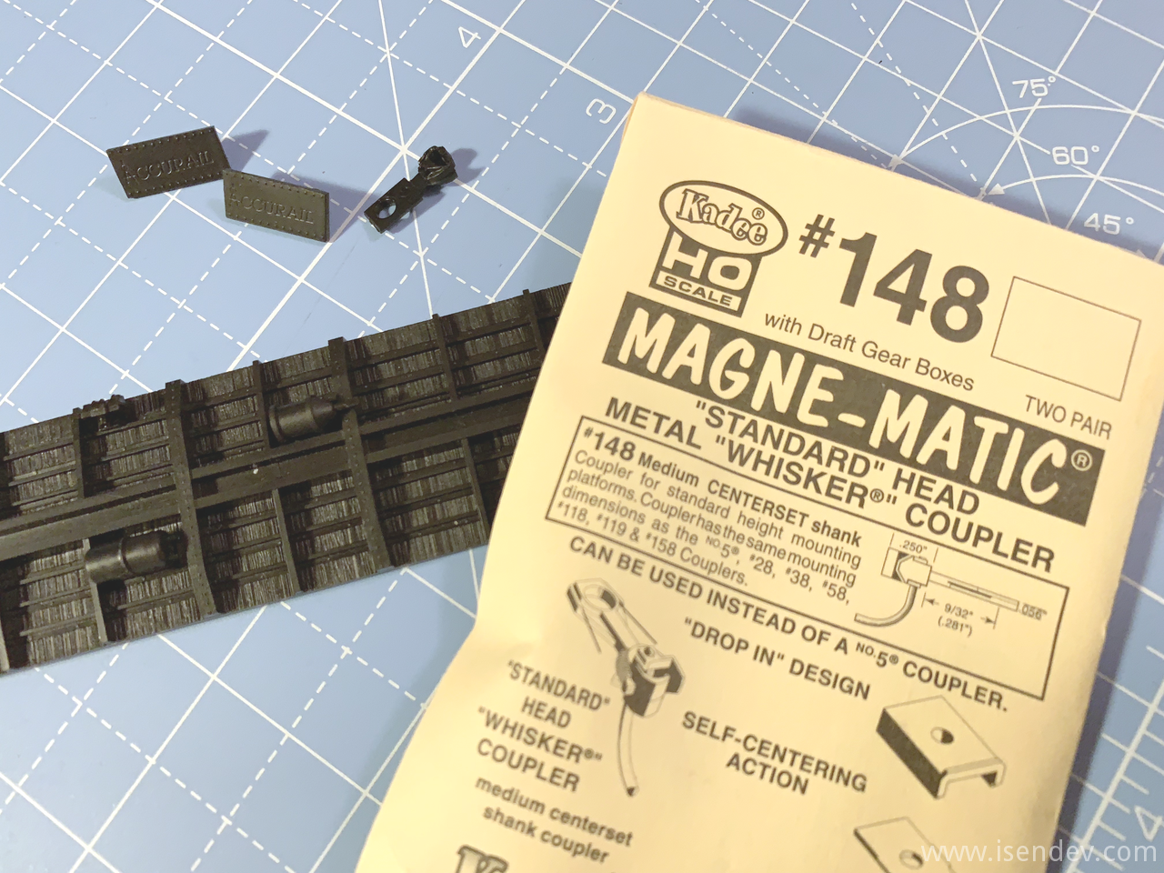
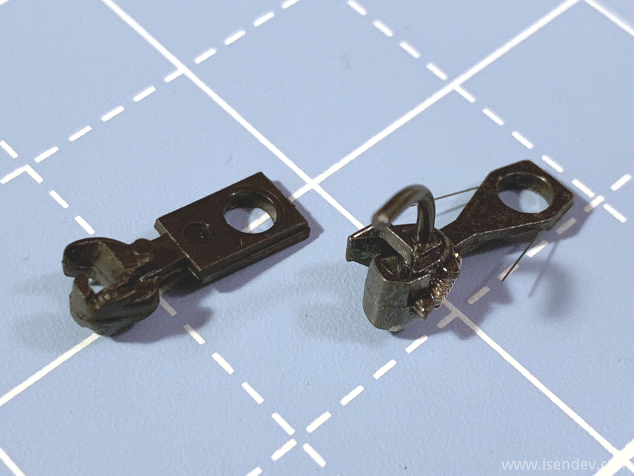
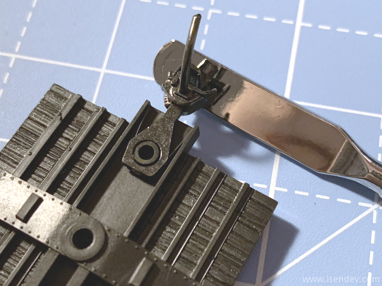
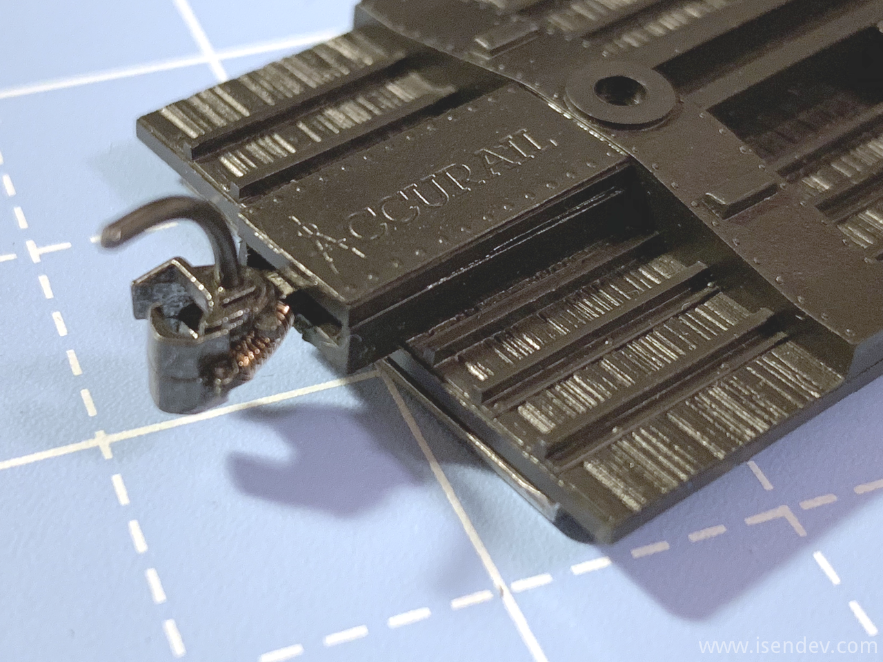
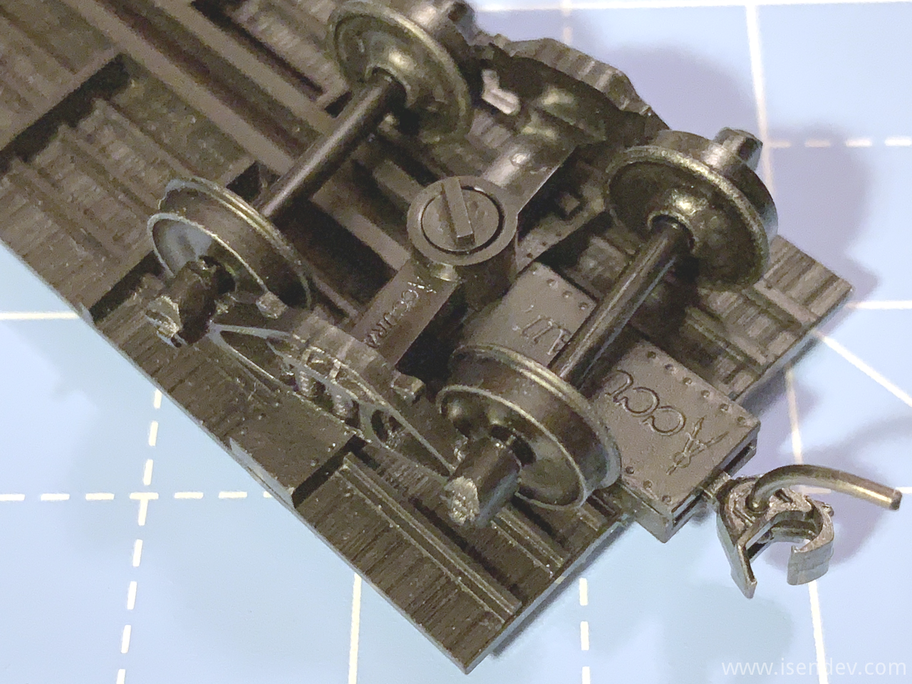
Old Accurail kits came with nearly non-funcional plastic couplers (newer kits came with much better Accumate couplers), so I've replaced them with some Kadee #148 Magne-Matic couplers.
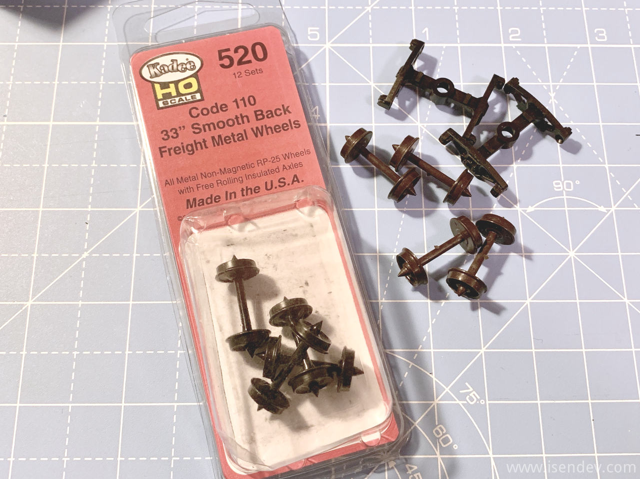
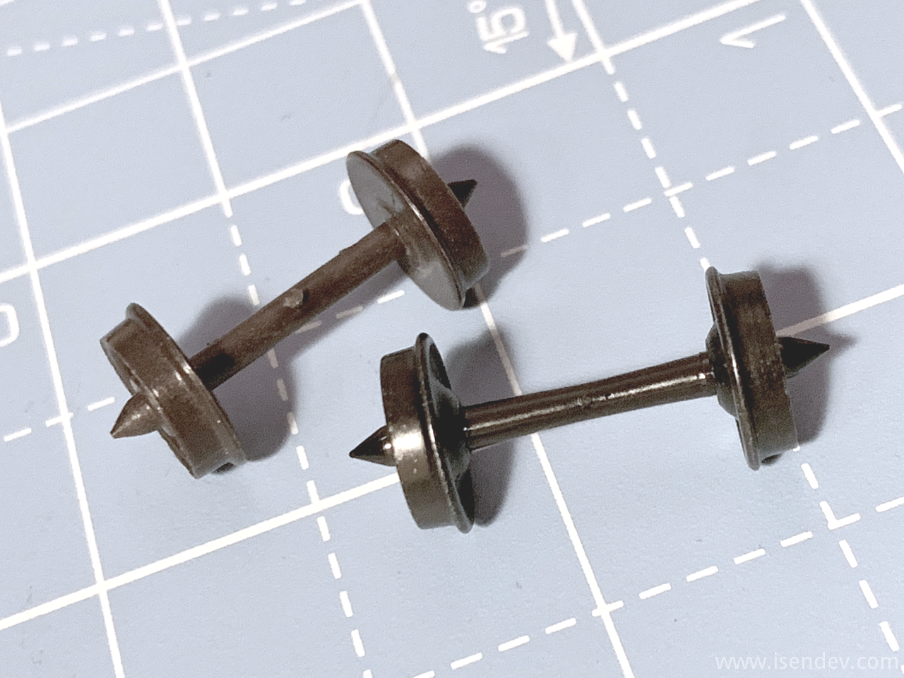
Another upgrade: Stock plastic wheelsets were replaced with Kadee 33" diameter smooth backed wheelsets (Kadee reference #520). These new wheelsets come with NMRA Code 110 profile (US National Model Railroad Association standard H0 gauge) and are compatible with my Trix C-Track layout.
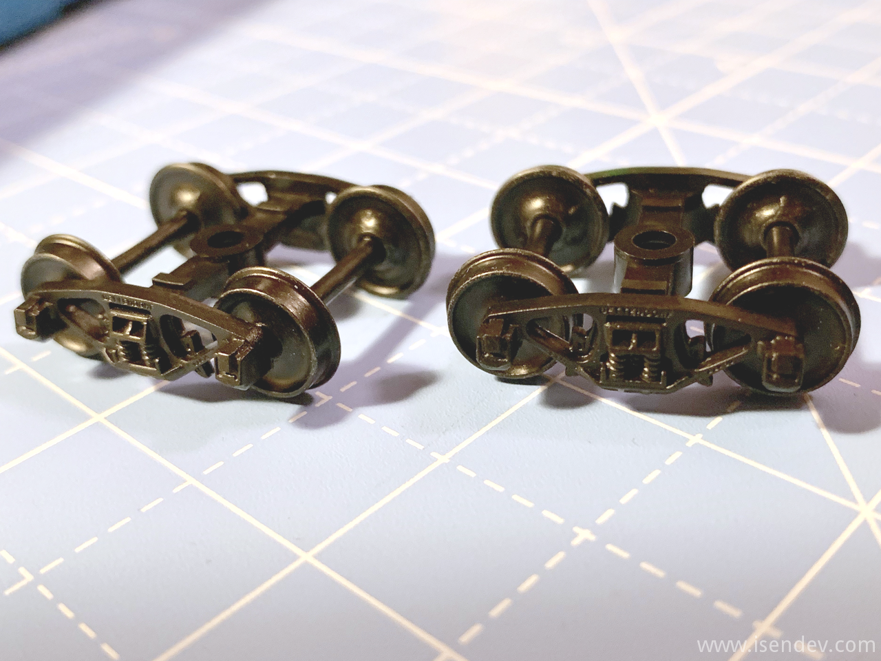
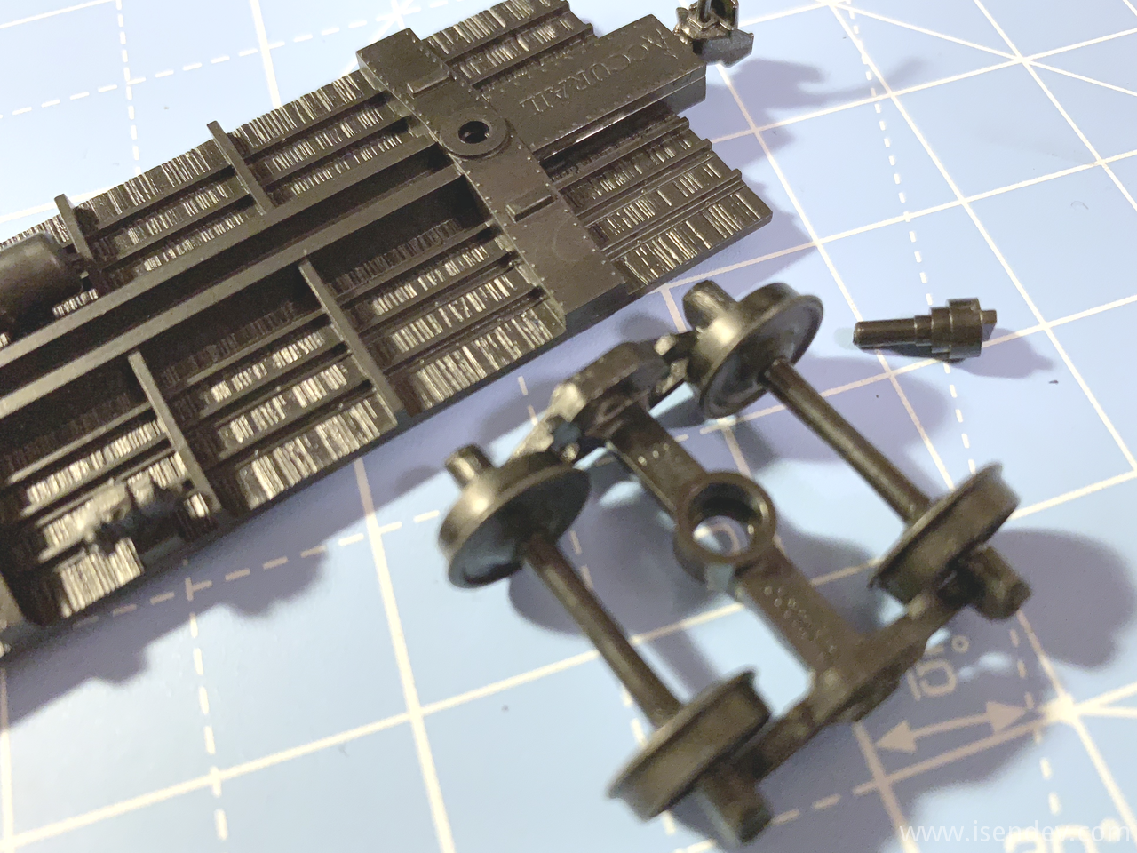
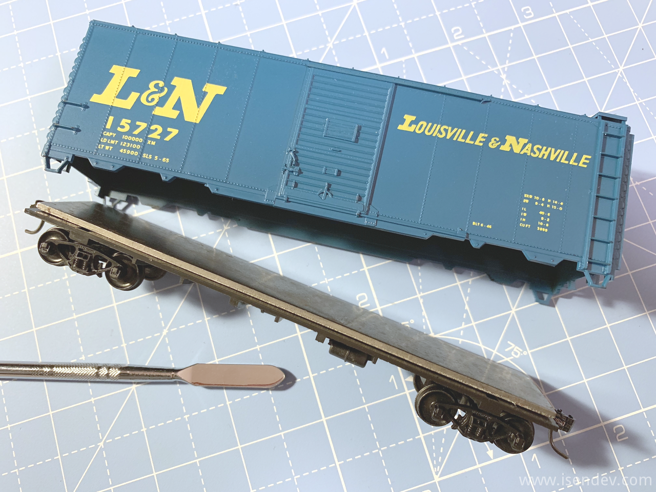
Once the trucks were installed, I only had to join the box to the chassis to finish the car.
I think that I'm going to buy some decal paper and try to renumber the box cars. I don't like that all of them have the same road number...
Pioneer SA-5300 restoration: Part IV. Other modifications.
By isendev.
Posted on 2017/08/03 22:44.
Tagged as: audio, diy, vintage, pioneer.
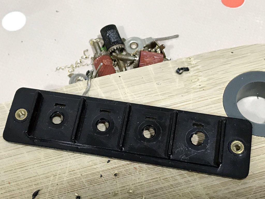
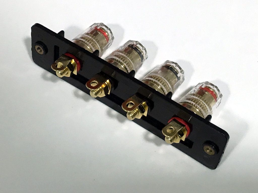
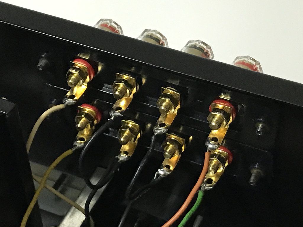
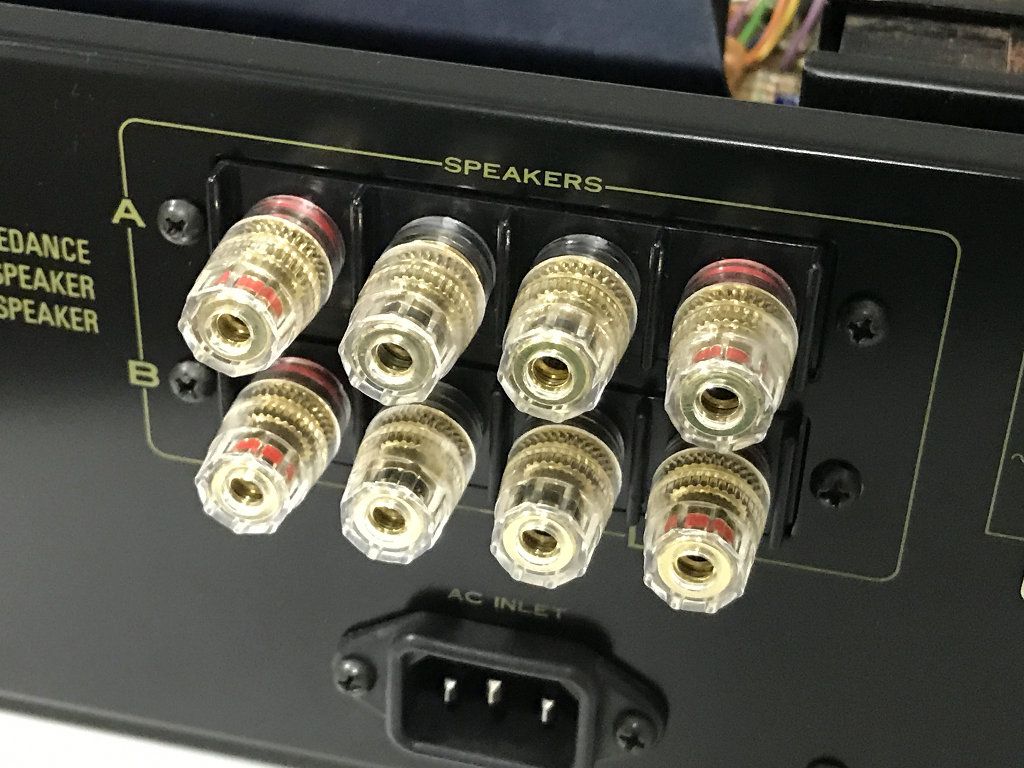
Here are some photos of two modifications I've made to improve the amplifier.
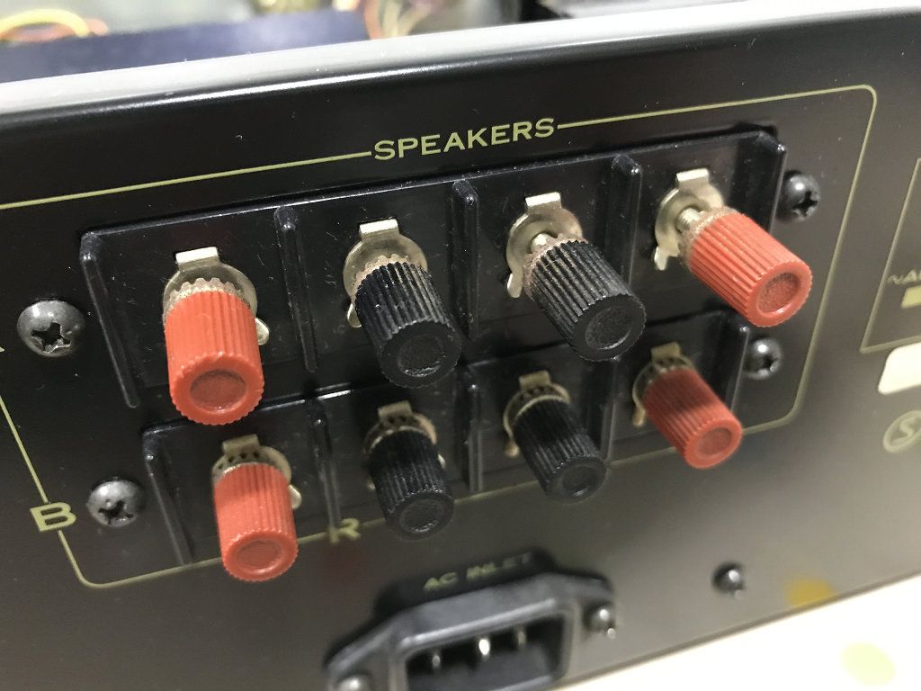
I've replaced the old and rusty speaker terminals with some new golden plated banana plug terminals:
This amplifier do not have an AC input EMI filter, so I've installed one to reduce power-line interference problems.

Pioneer SA-5300 restoration: Part III. Cleaning and testing.
By isendev.
Posted on 2017/06/25 20:10.
Tagged as: audio, diy, vintage, pioneer.
Previously, I've removed the top cover and the aluminium front panel and knobs to access the inners of the amplifier. Over the many years of use, control knobs and front panel tend to accumulate a lot of grime and grease. To make the aluminium parts shine again, nothing better than wash the surfaces gently with hot water and neutral soap. Carefully wipe with a wet microfiber cloth, to avoid damaging the front panel lettering.

Remounting ...

... and testing.

After recapping, the sound stage has improved considerably. This little amplifier sounds really, really good.
Pioneer SA-5300 restoration: Part II. Recapping.
By isendev.
Posted on 2017/04/26 19:35.
Tagged as: audio, diy, vintage, pioneer.
This new blog entry gathers some information about recapping, or the dark art of replacing the capacitors in vintage audio gear. As I stated on my previous blog entry, the electrolytic capacitors tend to decrease its perfomance through the years, and it's a common practice to replace all of them in audio equipment with more than 20 years old. Nowadays, good quality capacitors have better electric characteristics and smaller footprint, and can be easily found on online shops.
To make the task of replacing the caps easier, it's a good idea to grab a copy of the unit's service manual. Some small capacitor's values can be tricky to decode and a look to the schematic can help us a lot. Below you can find the complete Pioneer SA-5300 schematic that I've restored in one single image from various parts obtained browsing the net.

Once all capacitor values were identified, I ordered new parts using Panasonic low ESR references (FM and FC series) when available on RS Online, my shop of reference when searching for electronic components. The result: a lot of little plastic bags filled with shiny new caps ready to be installed.

One by one, all old capacitors were removed from the PCB and replaced with its new Panasonic equivalents. This task is not complicated, given the simplicity of the amplifier's board PCB layout. All the capacitors are easily reached without removing the PCB from the chassis. Once all elements are replaced, the difference in size between components is easily visible.

On the table, a bunch of old electrolytic capacitors, some of them with signs of leaking badly.

Bonus: The power indicator bulb was blown. At first I thought of replacing the bulb with a led connected to the amplifier's DC section, but fortunately I found a store in Madrid where these small bulbs were available. I desoldered the blown bulb from the AC supply wires and reconnected to the new bulb, insulated the joints and reattached to the holder using hot glue.

Next stop: cleaning and testing.