Showing entries tagged as: diy
Pioneer SA-5300 restoration: Part III. Cleaning and testing.
By isendev.
Posted on 2017/06/25 20:10.
Tagged as: audio, diy, vintage, pioneer.
Previously, I've removed the top cover and the aluminium front panel and knobs to access the inners of the amplifier. Over the many years of use, control knobs and front panel tend to accumulate a lot of grime and grease. To make the aluminium parts shine again, nothing better than wash the surfaces gently with hot water and neutral soap. Carefully wipe with a wet microfiber cloth, to avoid damaging the front panel lettering.
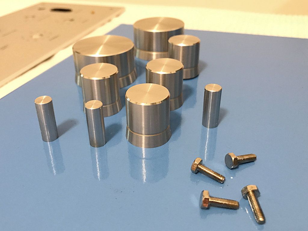
Remounting ...
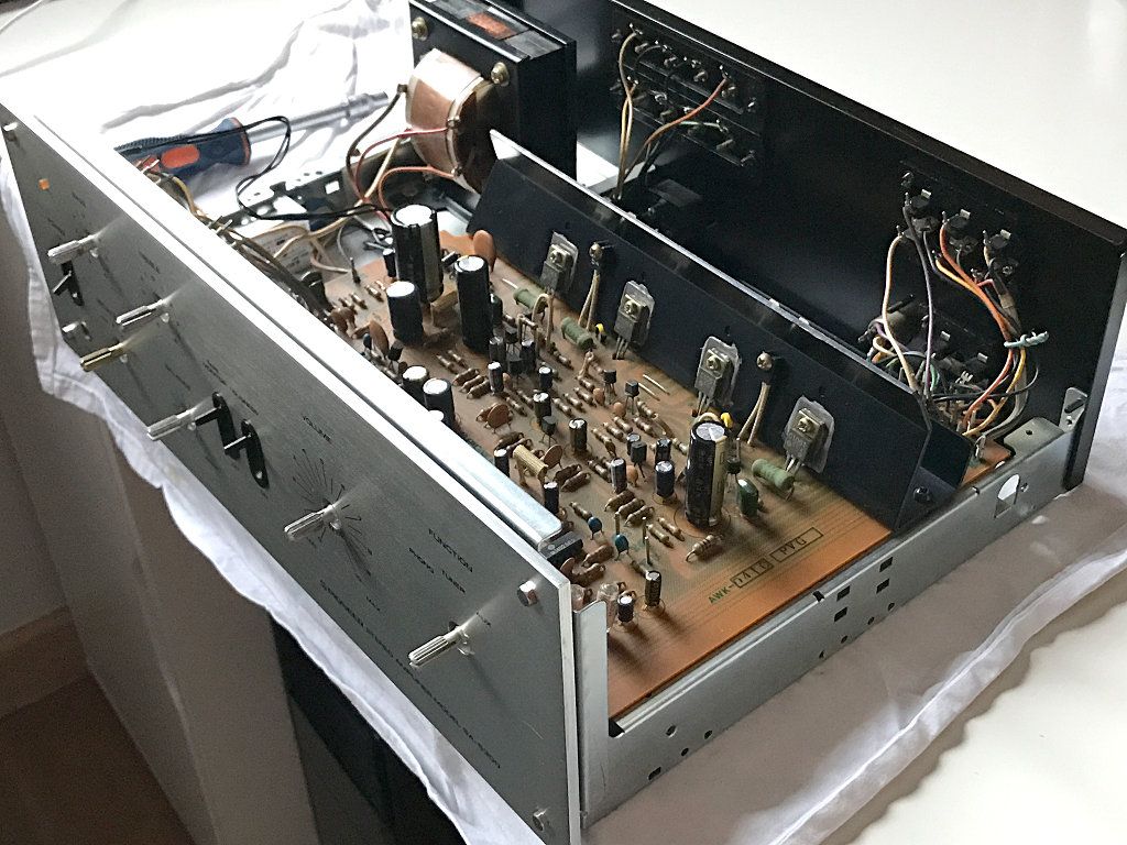
... and testing.
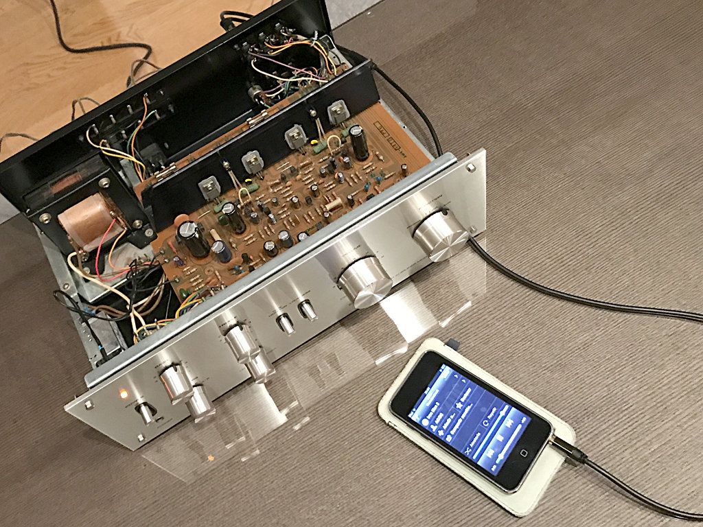
After recapping, the sound stage has improved considerably. This little amplifier sounds really, really good.
Pioneer SA-5300 restoration: Part II. Recapping.
By isendev.
Posted on 2017/04/26 19:35.
Tagged as: audio, diy, vintage, pioneer.
This new blog entry gathers some information about recapping, or the dark art of replacing the capacitors in vintage audio gear. As I stated on my previous blog entry, the electrolytic capacitors tend to decrease its perfomance through the years, and it's a common practice to replace all of them in audio equipment with more than 20 years old. Nowadays, good quality capacitors have better electric characteristics and smaller footprint, and can be easily found on online shops.
To make the task of replacing the caps easier, it's a good idea to grab a copy of the unit's service manual. Some small capacitor's values can be tricky to decode and a look to the schematic can help us a lot. Below you can find the complete Pioneer SA-5300 schematic that I've restored in one single image from various parts obtained browsing the net.
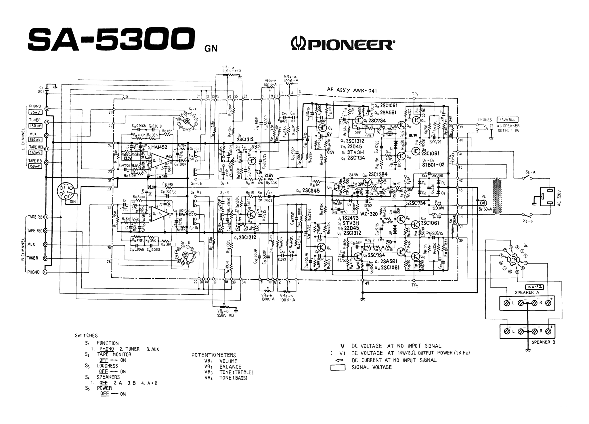
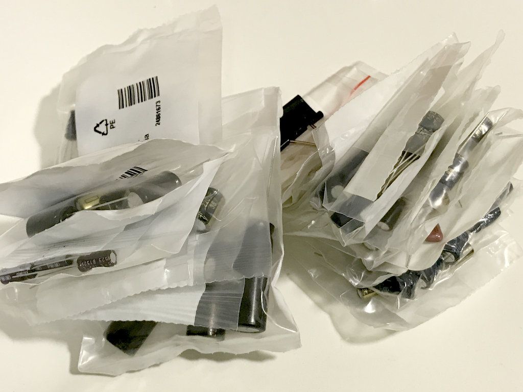
Once all capacitor values were identified, I ordered new parts using Panasonic low ESR references (FM and FC series) when available on RS Online, my shop of reference when searching for electronic components. The result: a lot of little plastic bags filled with shiny new caps ready to be installed.
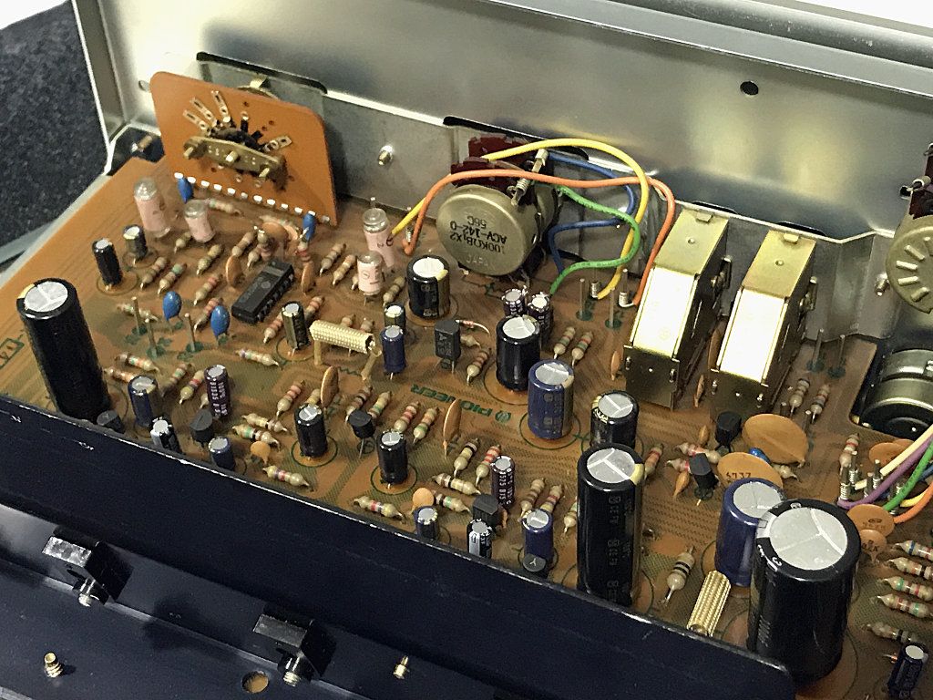
One by one, all old capacitors were removed from the PCB and replaced with its new Panasonic equivalents. This task is not complicated, given the simplicity of the amplifier's board PCB layout. All the capacitors are easily reached without removing the PCB from the chassis. Once all elements are replaced, the difference in size between components is easily visible.
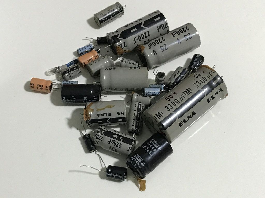
On the table, a bunch of old electrolytic capacitors, some of them with signs of leaking badly.
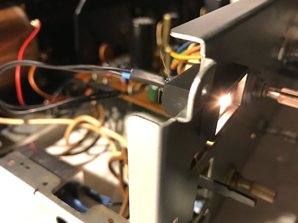
Bonus: The power indicator bulb was blown. At first I thought of replacing the bulb with a led connected to the amplifier's DC section, but fortunately I found a store in Madrid where these small bulbs were available. I desoldered the blown bulb from the AC supply wires and reconnected to the new bulb, insulated the joints and reattached to the holder using hot glue.
Next stop: cleaning and testing.
Pioneer SA-5300 restoration: Part I. Dissasemble and Cleaning.
By isendev.
Posted on 2017/01/24 22:53.
Tagged as: audio, diy, vintage, pioneer.
This is one of my latest projects and my first approach to vintage audio equipment restoration. I recently got my hands on this beautiful 70's amplifier: a Pioneer SA-5300. This little japanese machine was made around 1975 and is capable of output 10 watts per channel (8 Ohms), with a frequency response of 20Hz to 30kHz and a total harmonic distortion of 0.08%. Apparently the amplifier is in good condition, and it will not take much work to make it shiny and working.
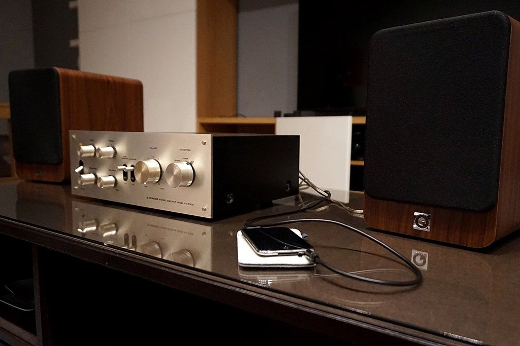
Once at home, I was able to test the amplifier paired with my trusty Q-Acoustics 2020i speakers. First impression was very positive. Nice sound, warm and detailed. Really impressive for a Pioneer "entry level" model. Beats hands down the stereo capabilities of my mid-range 2014 Yamaha home cinema receiver. The power bulb is blown and seems to have some minor problems on left channel when using the volume knob (nothing a good contact cleaner can not solve). Apart from those little problems, I have not found anything really important.
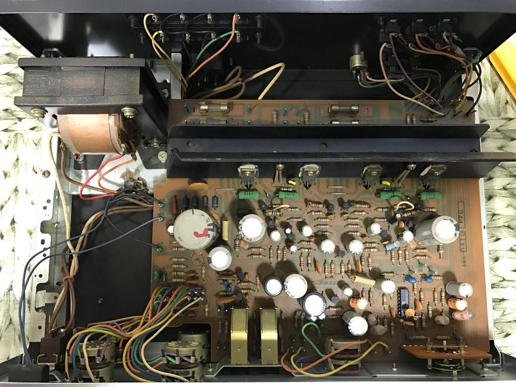
The image above shows the simplicity of the amplifier's internal layout: an AC transformer, front panel basic controls (switches and potentiometers), three input/output panels on the back and all these elements connected to only one board. This PCB shows the same level of simplicity as the rest of the unit, with evenly distributed components and thick tracks. Great for beginners who want to start learning how to restore vintage electronic equipment.
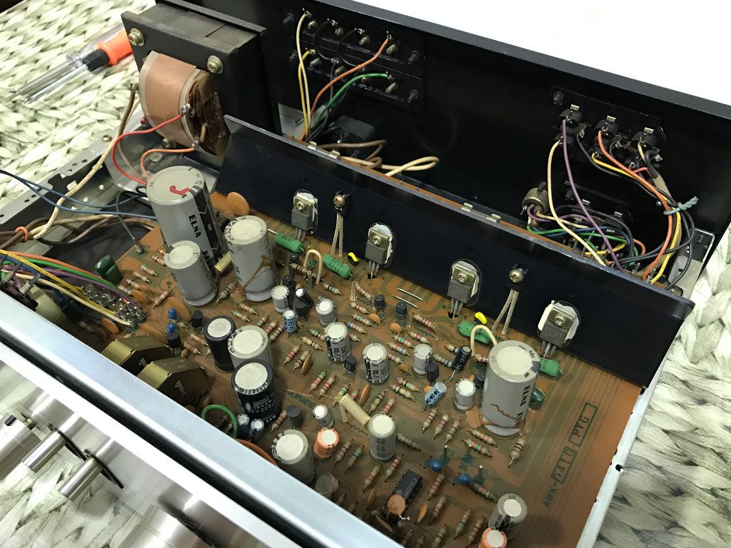
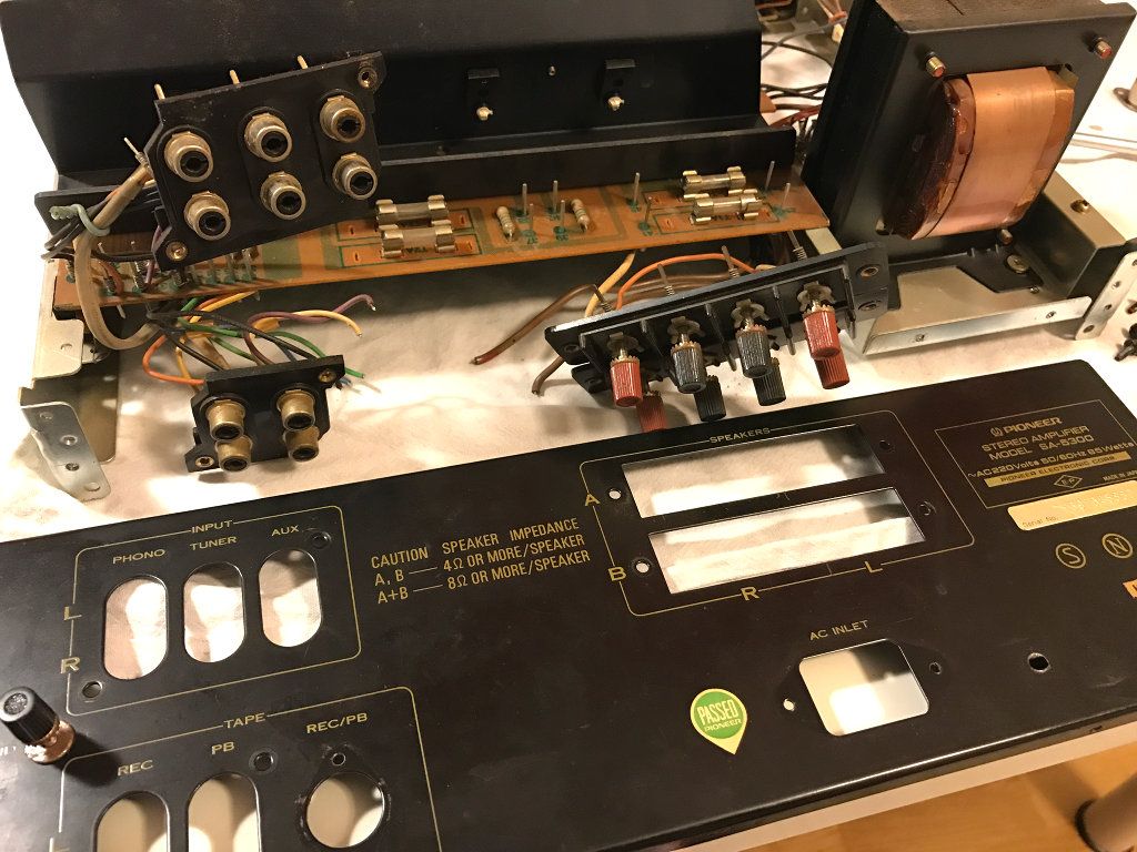
A first pass of compressed air removes all dust accumulated over the years, but in order to clean the all the grim properly (using water and soap), some components must be disconnected from the chassis. For example, to remove the back panel, some cables must be dettached from its connectors and resoldered on reassemble.
To replace the aged thermal grease on the transistors, the aluminium heatsink must be detached from the PCB. Special care must be taken when separating the transistors from the aluminum surface and when cleaning the traces of thermal grease: it's very easy to damage transistor's legs.
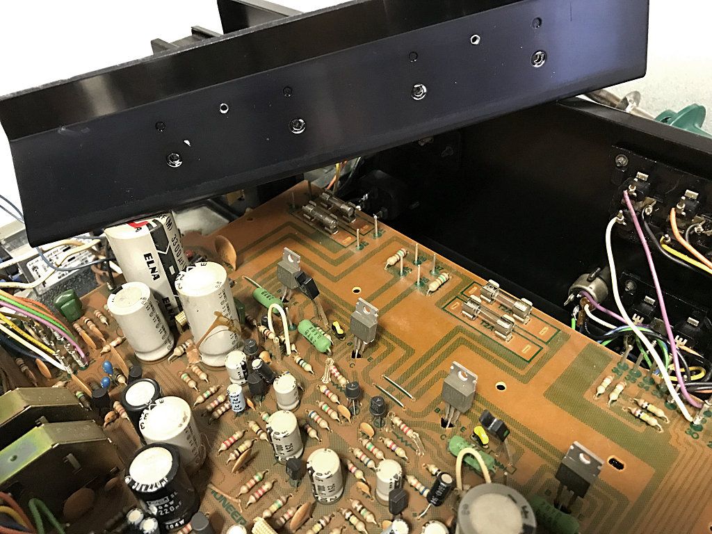
Once aged compound has been removed from heatsink and transistors, it's time to reassemble using brand new mica insulating washers and fresh thermal grease. The detailed cleaning of the rest of the components is done using soft brushes and PCB cleaner.
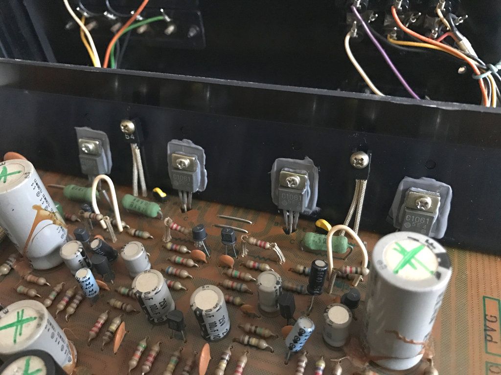
After cleaning is completed, the next step will be to replace all electrolytic capacitors. Why? Capacitors are the most failure-prone components in old electronic equipment, and is a common practice to replace all of a set's electrolytic capacitors to restore the original performance. In the next blog entry I will explain how I have done this recapping task.
Raspberry Pi + LCD + Python (System Information)
By isendev.
Posted on 2014/01/14 22:07.
Tagged as: hardware, programming, diy, python.
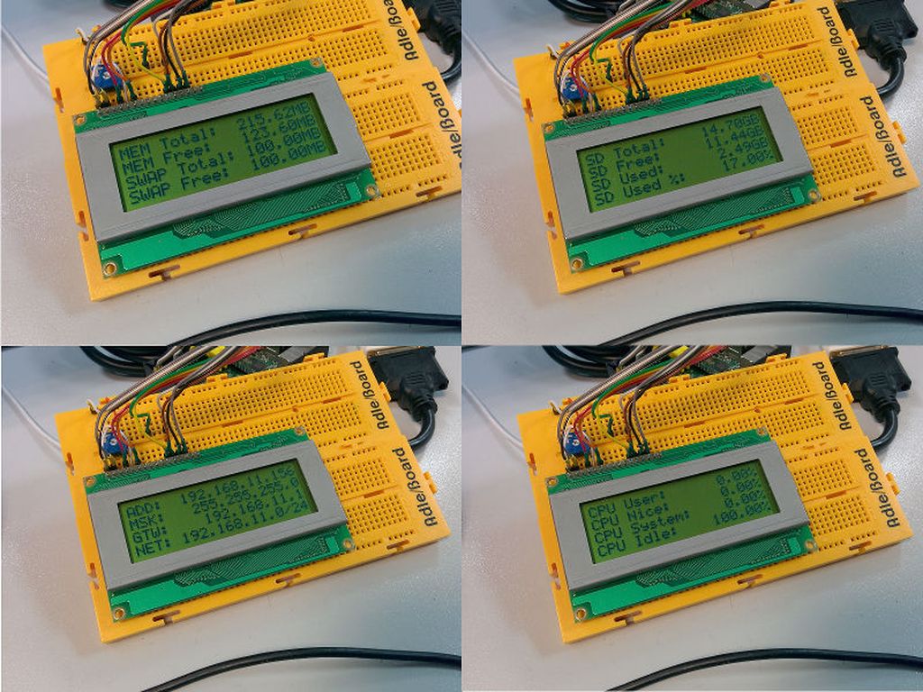
Here is the Python code to use the HD44780 compatible LCD as a simple, but quite useful, system information monitor. The source has been separated in 3 files, for better understanding (lcd.py, sysinfo.py and lcd.sysinfo.py). It currently shows Memory, CPU, Filesystem and Network information, but can be easily modified to include other information provided by PSUtil (process and netstat information, I/O statistics, etc.).
<lcd.py>
Functions used to manage the 20x4 LCD display through the Raspberry Pi GPIO port.
#!/usr/bin/python
# 20x4 LCD Control Functions.
# Original code by: Matt Hawkins
# Site: http://www.raspberrypi-spy.co.uk
# Modified by: Antonio Perdices.
# Site: https://www.isendev.com
# 14/01/2014

# LCD Wiring.
# 1 : GND                    - TO GROUND
# 2 : 5V                     - TO +5V
# 3 : Contrast (0-5V)        - TO 10K POT OUTPUT
# 4 : RS (Register Select)
# 5 : R/W (Read Write)       - TO GROUND
# 6 : Enable or Strobe
# 7 : Data Bit 0             - NOT USED
# 8 : Data Bit 1             - NOT USED
# 9 : Data Bit 2             - NOT USED
# 10: Data Bit 3             - NOT USED
# 11: Data Bit 4
# 12: Data Bit 5
# 13: Data Bit 6
# 14: Data Bit 7
# 15: Backlight 5V           - NOT USED
# 16: Backlight GND          - NOT USED

# Imports.
import RPi.GPIO as GPIO
import time

# GPIO to LCD Mapping.
# Using Broadcom GPIO numbers
LCD_RS = 7
LCD_E  = 8
LCD_D4 = 25
LCD_D5 = 24
LCD_D6 = 23
LCD_D7 = 18

# Constants.

# Max chars per line.
LCD_WIDTH = 20

# LCD Byte Mode. 'Character' or 'Command'.
LCD_CHR = True
LCD_CMD = False

# 1st Line LCD RAM address.
LCD_LINE_1 = 0x80
# 2nd Line LCD RAM address.
LCD_LINE_2 = 0xC0
# 3rd Line LCD RAM address.
LCD_LINE_3 = 0x94
 # 4th Line LCD RAM address.
LCD_LINE_4 = 0xD4

# Timing constants.
E_PULSE = 0.00005
E_DELAY = 0.00005

# Enable GPIO.
def lcd_gpio_enable():

    # Disable warnings.
    GPIO.setwarnings(False)

    # Use Broadcom GPIO numbers.
    GPIO.setmode(GPIO.BCM)

    # Enable GPIO outputs.
    GPIO.setup(LCD_E, GPIO.OUT)  # E
    GPIO.setup(LCD_RS, GPIO.OUT) # RS
    GPIO.setup(LCD_D4, GPIO.OUT) # DB4
    GPIO.setup(LCD_D5, GPIO.OUT) # DB5
    GPIO.setup(LCD_D6, GPIO.OUT) # DB6
    GPIO.setup(LCD_D7, GPIO.OUT) # DB7

# Init display function.
def lcd_init():

    # Init commands.
    lcd_byte(0x33,LCD_CMD)
    lcd_byte(0x32,LCD_CMD)
    lcd_byte(0x28,LCD_CMD)
    lcd_byte(0x0C,LCD_CMD)
    lcd_byte(0x06,LCD_CMD)
    lcd_byte(0x01,LCD_CMD)

# Send byte data to display.
# bits = data.
# mode = 'True' for character or 'False' for command.
def lcd_byte(bits, mode):

    # Register Select.
    GPIO.output(LCD_RS, mode)

    # Send High bits.
    GPIO.output(LCD_D4, False)
    GPIO.output(LCD_D5, False)
    GPIO.output(LCD_D6, False)
    GPIO.output(LCD_D7, False)
    if bits&0x10==0x10:
        GPIO.output(LCD_D4, True)
    if bits&0x20==0x20:
        GPIO.output(LCD_D5, True)
    if bits&0x40==0x40:
        GPIO.output(LCD_D6, True)
    if bits&0x80==0x80:
        GPIO.output(LCD_D7, True)

    # Toggle 'Enable' pin.
    time.sleep(E_DELAY)
    GPIO.output(LCD_E, True)
    time.sleep(E_PULSE)
    GPIO.output(LCD_E, False)
    time.sleep(E_DELAY)

    # Low bits.
    GPIO.output(LCD_D4, False)
    GPIO.output(LCD_D5, False)
    GPIO.output(LCD_D6, False)
    GPIO.output(LCD_D7, False)
    if bits&0x01==0x01:
        GPIO.output(LCD_D4, True)
    if bits&0x02==0x02:
        GPIO.output(LCD_D5, True)
    if bits&0x04==0x04:
        GPIO.output(LCD_D6, True)
    if bits&0x08==0x08:
        GPIO.output(LCD_D7, True)

    # Toggle 'Enable' pin
    time.sleep(E_DELAY)
    GPIO.output(LCD_E, True)
    time.sleep(E_PULSE)
    GPIO.output(LCD_E, False)
    time.sleep(E_DELAY)

# Send string to display.
# Style parameter:
# 1 = Left justified.
# 2 = Centred.
# 3 = Right justified.
def lcd_string(message,style):

    if style==1:
        message = message.ljust(LCD_WIDTH," ")
    elif style==2:
        message = message.center(LCD_WIDTH," ")
    elif style==3:
        message = message.rjust(LCD_WIDTH," ")

    for i in range(LCD_WIDTH):
        lcd_byte(ord(message[i]),LCD_CHR)

# Blank LCD.
def lcd_clear():

    lcd_byte(LCD_LINE_1, LCD_CMD)
    lcd_string("",2)
    lcd_byte(LCD_LINE_2, LCD_CMD)
    lcd_string("",2)
    lcd_byte(LCD_LINE_3, LCD_CMD)
    lcd_string("",2)
    lcd_byte(LCD_LINE_4, LCD_CMD)
    lcd_string("",2)
<sysinfo.py>
Functions to get system information using PSUtil, a cross-platform process and system utilities module for Python.
#!/usr/bin/python
# System Information Functions.
# Author: Antonio Perdices.
# Site: https://www.isendev.com
# 14/01/2014

# Imports.
import lcd
import psutil
import subprocess

# Show memory info.
def lcd_show_mem():

    MEM_TOTAL_LABEL = "MEM Total:"
    MEM_TOTAL = "%(mem).2fMB" % {'mem': psutil.virtual_memory().total/1024.0/1024.0}
    MEM_TOTAL = MEM_TOTAL.rjust(lcd.LCD_WIDTH - len(MEM_TOTAL_LABEL)," ")

    MEM_FREE_LABEL = "MEM Free:"
    MEM_FREE = "%(mem).2fMB" % {'mem': psutil.virtual_memory().free/1024.0/1024.0}
    MEM_FREE = MEM_FREE.rjust(lcd.LCD_WIDTH - len(MEM_FREE_LABEL)," ")

    SWAP_TOTAL_LABEL = "SWAP Total:"
    SWAP_TOTAL = "%(mem).2fMB" % {'mem': psutil.swap_memory().total/1024.0/1024.0}
    SWAP_TOTAL = SWAP_TOTAL.rjust(lcd.LCD_WIDTH - len(SWAP_TOTAL_LABEL)," ")

    SWAP_FREE_LABEL = "SWAP Free:"
    SWAP_FREE = "%(mem).2fMB" % {'mem': psutil.swap_memory().free/1024.0/1024.0}
    SWAP_FREE = SWAP_FREE.rjust(lcd.LCD_WIDTH - len(SWAP_FREE_LABEL)," ")

    lcd.lcd_byte(lcd.LCD_LINE_1, lcd.LCD_CMD)
    lcd.lcd_string(MEM_TOTAL_LABEL + MEM_TOTAL, 1)
    lcd.lcd_byte(lcd.LCD_LINE_2, lcd.LCD_CMD)
    lcd.lcd_string(MEM_FREE_LABEL + MEM_FREE, 1)
    lcd.lcd_byte(lcd.LCD_LINE_3, lcd.LCD_CMD)
    lcd.lcd_string(SWAP_TOTAL_LABEL + SWAP_TOTAL, 1)
    lcd.lcd_byte(lcd.LCD_LINE_4, lcd.LCD_CMD)
    lcd.lcd_string(SWAP_FREE_LABEL + SWAP_FREE, 1)

# Show cpu info.
def lcd_show_cpu():

    CPU_READ = psutil.cpu_times_percent(interval=1, percpu=False)

    CPU_USER_LABEL = "CPU User:"
    CPU_USER = "%(cpu).2f%%" % {'cpu': CPU_READ.user}
    CPU_USER = CPU_USER.rjust(lcd.LCD_WIDTH - len(CPU_USER_LABEL)," ")

    CPU_NICE_LABEL = "CPU Nice:"
    CPU_NICE = "%(cpu).2f%%" % {'cpu': CPU_READ.nice}
    CPU_NICE = CPU_NICE.rjust(lcd.LCD_WIDTH - len(CPU_NICE_LABEL)," ")

    CPU_SYSTEM_LABEL = "CPU System:"
    CPU_SYSTEM = "%(cpu).2f%%" % {'cpu': CPU_READ.system}
    CPU_SYSTEM = CPU_SYSTEM.rjust(lcd.LCD_WIDTH - len(CPU_SYSTEM_LABEL)," ")

    CPU_IDLE_LABEL = "CPU Idle:"
    CPU_IDLE = "%(cpu).2f%%" % {'cpu': CPU_READ.idle}
    CPU_IDLE = CPU_IDLE.rjust(lcd.LCD_WIDTH - len(CPU_IDLE_LABEL)," ")

    lcd.lcd_byte(lcd.LCD_LINE_1, lcd.LCD_CMD)
    lcd.lcd_string(CPU_USER_LABEL + CPU_USER, 1)
    lcd.lcd_byte(lcd.LCD_LINE_2, lcd.LCD_CMD)
    lcd.lcd_string(CPU_NICE_LABEL + CPU_NICE, 1)
    lcd.lcd_byte(lcd.LCD_LINE_3, lcd.LCD_CMD)
    lcd.lcd_string(CPU_SYSTEM_LABEL + CPU_SYSTEM, 1)
    lcd.lcd_byte(lcd.LCD_LINE_4, lcd.LCD_CMD)
    lcd.lcd_string(CPU_IDLE_LABEL + CPU_IDLE, 1)

# Show filesystem info.
def lcd_show_fsinfo():

    FS_READ = psutil.disk_usage('/')

    FS_TOTAL_LABEL = "SD Total:"
    FS_TOTAL = "%(disk).2fGB" % {'disk': FS_READ.total/1024.0/1024.0/1024.0}
    FS_TOTAL = FS_TOTAL.rjust(lcd.LCD_WIDTH - len(FS_TOTAL_LABEL)," ")

    FS_FREE_LABEL = "SD Free:"
    FS_FREE = "%(disk).2fGB" % {'disk': FS_READ.free/1024.0/1024.0/1024.0}
    FS_FREE = FS_FREE.rjust(lcd.LCD_WIDTH - len(FS_FREE_LABEL)," ")

    FS_USED_LABEL = "SD Used:"
    FS_USED = "%(disk).2fGB" % {'disk': FS_READ.used/1024.0/1024.0/1024.0}
    FS_USED = FS_USED.rjust(lcd.LCD_WIDTH - len(FS_USED_LABEL)," ")

    FS_PERCENT_LABEL = "SD Used %:"
    FS_PERCENT = "%(disk).2f%%" % {'disk': FS_READ.percent}
    FS_PERCENT = FS_PERCENT.rjust(lcd.LCD_WIDTH - len(FS_PERCENT_LABEL)," ")

    lcd.lcd_byte(lcd.LCD_LINE_1, lcd.LCD_CMD)
    lcd.lcd_string(FS_TOTAL_LABEL + FS_TOTAL, 1)
    lcd.lcd_byte(lcd.LCD_LINE_2, lcd.LCD_CMD)
    lcd.lcd_string(FS_FREE_LABEL + FS_FREE, 1)
    lcd.lcd_byte(lcd.LCD_LINE_3, lcd.LCD_CMD)
    lcd.lcd_string(FS_USED_LABEL + FS_USED, 1)
    lcd.lcd_byte(lcd.LCD_LINE_4, lcd.LCD_CMD)
    lcd.lcd_string(FS_PERCENT_LABEL + FS_PERCENT, 1)

# Show network info.
def lcd_show_netinfo(interface):

    IP_READ = subprocess.check_output(["/sbin/ifconfig", interface])

    IP_ADDRESS_LABEL = "ADD:"
    if not "addr:" in IP_READ:
        IP_ADDRESS = "0.0.0.0"
    else:
        IP_ADDRESS = IP_READ.split("\n")[1].split()[1][5:]
    IP_ADDRESS = IP_ADDRESS.rjust(lcd.LCD_WIDTH - len(IP_ADDRESS_LABEL)," ")

    IP_MASK_LABEL = "MSK:"
    if not "addr:" in IP_READ:
        IP_MASK = "0.0.0.0"
    else:
        IP_MASK = IP_READ.split("\n")[1].split()[3][5:]
    IP_MASK = IP_MASK.rjust(lcd.LCD_WIDTH - len(IP_MASK_LABEL)," ")

    IP_READ = subprocess.check_output(["/sbin/ip", "route"])

    IP_GW_LABEL = "GTW:"
    if not "default" in IP_READ:
        IP_GW = "0.0.0.0"
    else:
        IP_GW = IP_READ.split("\n")[0].split()[2]
    IP_GW = IP_GW.rjust(lcd.LCD_WIDTH - len(IP_GW_LABEL)," ")

    IP_NET_LABEL = "NET:"
    if not "default" in IP_READ:
        IP_NET = "0.0.0.0"
    else:
        IP_NET = IP_READ.split("\n")[1].split()[0]
    IP_NET = IP_NET.rjust(lcd.LCD_WIDTH - len(IP_NET_LABEL)," ")

    lcd.lcd_byte(lcd.LCD_LINE_1, lcd.LCD_CMD)
    lcd.lcd_string(IP_ADDRESS_LABEL + IP_ADDRESS, 1)
    lcd.lcd_byte(lcd.LCD_LINE_2, lcd.LCD_CMD)
    lcd.lcd_string(IP_MASK_LABEL + IP_MASK, 1)
    lcd.lcd_byte(lcd.LCD_LINE_3, lcd.LCD_CMD)
    lcd.lcd_string(IP_GW_LABEL + IP_GW, 1)
    lcd.lcd_byte(lcd.LCD_LINE_4, lcd.LCD_CMD)
    lcd.lcd_string(IP_NET_LABEL + IP_NET, 1)
<lcd.sysinfo.py>
Main program.
#!/usr/bin/python
# 20x4 LCD System Information Script for Raspberry Pi.
# Author: Antonio Perdices.
# Site: https://www.isendev.com
# 14/01/2014

# Imports.
import time
import lcd
import sysinfo

LOOP_TIME = 5

# Main program.
def main():

    # Enable GPIO.
    lcd.lcd_gpio_enable()

    # Init display.
    lcd.lcd_init()

    # Write message to console.
    # print("Press Ctrl+C to exit...")

    COUNTER = 1

    # Main loop.
    while True:

        if (COUNTER % 4 == 0):
            sysinfo.lcd_show_mem()
            COUNTER = COUNTER + 1
        elif (COUNTER % 4 == 1):
            sysinfo.lcd_show_cpu()
            COUNTER = COUNTER + 1
        elif (COUNTER % 4 == 2):
            sysinfo.lcd_show_netinfo("eth0")
            COUNTER = COUNTER + 1
        else:
            sysinfo.lcd_show_fsinfo()
            COUNTER = 0

        time.sleep(LOOP_TIME)

# Execute main program.
if __name__ == '__main__':
    try:
        main()
    except KeyboardInterrupt:
        print("\nKeyboard interrupt detected... Bye!")
        lcd.lcd_clear()
        pass
<lcd.init>
If you want to run the display program at startup, here is an init script for Debian.
### BEGIN INIT INFO
# Provides: LCD - CPU / Memory / Filesystem / Network
# Required-Start: $remote_fs $syslog
# Required-Stop: $remote_fs $syslog
# Default-Start: 2 3 4 5
# Default-Stop: 0 1 6
# Short-Description: Liquid Crystal Display
# Description: LCD - CPU / Memory / Filesystem / Network
### END INIT INFO

#! /bin/sh
# /etc/init.d/lcd

export HOME
case "$1" in
    start)
        echo "Starting LCD..."
        /root/Dev.LCD/lcd.sysinfo/lcd.sysinfo.py 2>&1 &
    ;;
    stop)
        echo "Stopping LCD..."
        LCD_PID=`ps auxwww | grep lcd.sysinfo.py | head -1 | awk '{print $2}'`
        kill -9 $LCD_PID
    ;;
    *)
        echo "Usage: /etc/init.d/lcd {start|stop}"
        exit 1
    ;;
esac
exit 0